EasyManua.ls Logo

Denon DR-M33HX - FF and REW Time Check; ADJUSTING THE ELECTRICAL SECTIONS; Tape Transport Check and Azimuth Adjustment; Tape Speed Check and Adjustment

Denon DR-M33HX
48 pages
Print Icon
To Next Page IconTo Next Page
To Previous Page IconTo Previous Page
Loading...
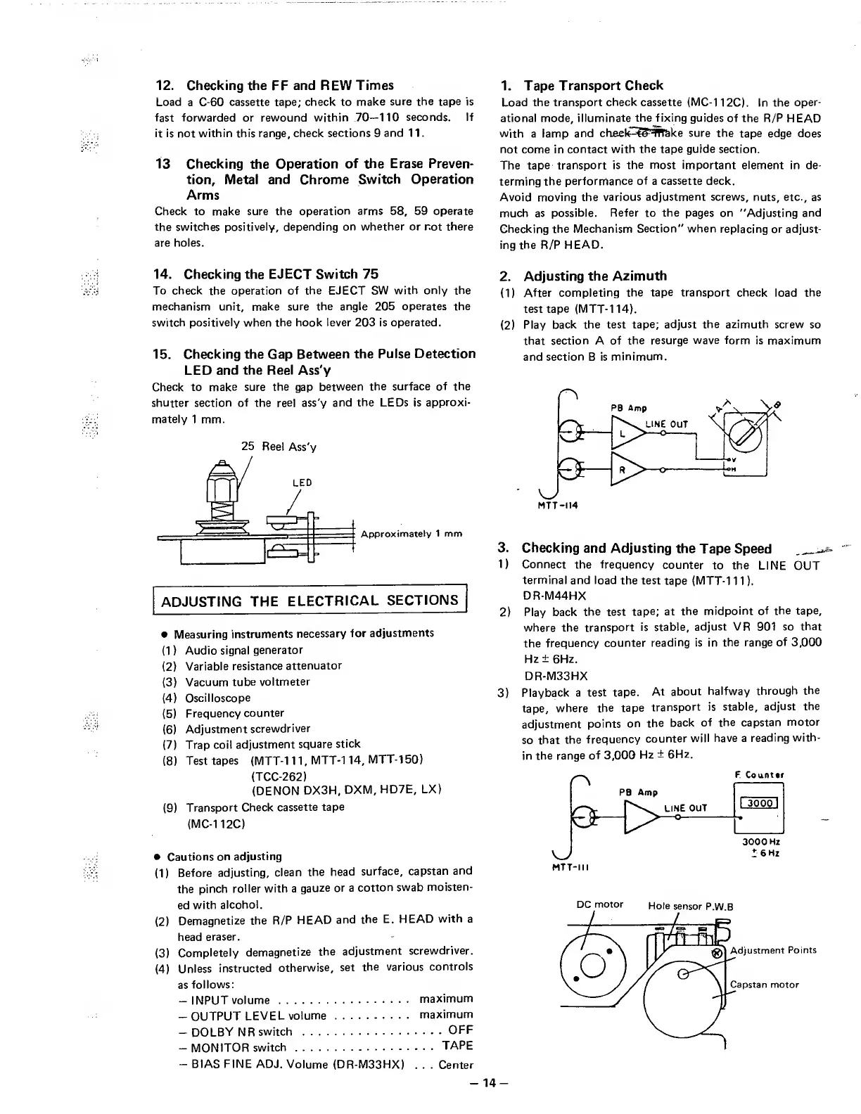
12.
Checking
the
FF
and
REW
Times
Load
a
C-60
cassette
tape;
check
to
make
sure
the
tape
is
fast
forwarded
or
rewound
within
70—110
seconds.
If
it
is
not
within
this
range,
check
sections
9
and
11.
13
Checking
the
Operation
of
the
Erase
Preven¬
tion,
Metal
and
Chrome
Switch
Operation
Arms
Check
to
make
sure
the
operation
arms
58,
59
operate
the
switches
positively,
depending
on
whether
or
not
there
are
holes.
14.
Checking
the
EJECT
Switch
75
To
check
the
operation
of
the
EJECT
SW
with
only
the
mechanism
unit,
make
sure
the
angle
205
operates
the
switch
positively
when
the
hook
lever
203
is
operated.
15.
Checking
the
Gap
Between
the
Pulse
Detection
LED
and
the
Reel
Ass'y
Check
to
make
sure
the
gap
between
the
surface
of
the
shutter
section
of
the
reel
ass'y
and
the
LEDs
is
approxi¬
mately
1
mm.
25
Reel
Ass'y
•
Measuring
instruments
necessary
for
adjustments
(1)
Audio
signal
generator
(2)
Variable
resistance
attenuator
(3)
Vacuum
tube
voltmeter
(4)
Oscilloscope
(5)
Frequency
counter
(6)
Adjustment
screwdriver
(7)
Trap
coil
adjustment
square
stick
(8)
Test
tapes
(MTT-111,
MTT-114,
MTT-150)
(TCC-262)
(DENON
DX3H,
DXM,
HD7E,
LX)
(9)
Transport
Check
cassette
tape
(MC-112C)
•
Cautions
on
adjusting
(1)
Before
adjusting,
clean
the
head
surface,
capstan
and
the
pinch
roller
with
a
gauze
or
a
cotton
swab
moisten¬
ed
with
alcohol.
(2)
Demagnetize
the
R/P
HEAD
and
the
E.
HEAD
with
a
head
eraser.
(3)
Completely
demagnetize
the
adjustment
screwdriver.
(4)
Unless
instructed
otherwise,
set
the
various
controls
as
follows:
-INPUT
volume.
maximum
-
OUTPUT
LEVEL
volume.
maximum
-
DOLBY
NR
switch
.OFF
-
MONITOR
switch.TAPE
-
BIAS
FINE
ADJ.
Volume
(DR-IVI33HX)
.
.
.
Center
1.
Tape
Transport
Check
Load
the
transport
check
cassette
(MC-112C).
In
the
oper¬
ational
mode,
illuminate
the
fixing
guides
of
the
R/P
HEAD
with
a
lamp
and
cfiBek^fe-Wake
sure
the
tape
edge
does
not
come
in
contact
with
the
tape
guide
section.
The
tape
transport
is
the
most
important
element
in
de-
terming
the
performance
of
a
cassette
deck.
Avoid
moving
the
various
adjustment
screws,
nuts,
etc.,
as
much
as
possible.
Refer
to
the
pages
on
"Adjusting
and
Checking
the
Mechanism
Section"
when
replacing
or
adjust¬
ing
the
R/P
HEAD.
2.
Adjusting
the
Azimuth
(1)
After
completing
the
tape
transport
check
load
the
test
tape
(MTT-114).
(2)
Play
back
the
test
tape;
adjust
the
azimuth
screw
so
that
section
A
of
the
resurge
wave
form
is
maximum
and
section
B
is
minimum.
MTT-II4
3.
C
hecking
and
Adjusting
the
Tape
Speed
1)
Connect
the
frequency
counter
to
the
LINE
OUT
terminal
and
load
the
test
tape
(MTT-111).
DR-M44HX
2)
Play
back
the
test
tape;
at
the
midpoint
of
the
tape,
where
the
transport
is
stable,
adjust
VR
901
so
that
the
frequency
counter
reading
is
in
the
range
of
3,000
Hz±
6Hz.
DR-M33HX
3)
Playback
a
test
tape.
At
about
halfway
through
the
tape,
where
the
tape
transport
is
stable,
adjust
the
adjustment
points
on
the
back
of
the
capstan
motor
so
that
the
frequency
counter
will
have
a
reading
with¬
in
the
range
of
3,000
Hz
±
6Hz.
DC
motor
Hole
sensor
P.W.B
-
1
4
-

Table of Contents