EasyManua.ls Logo

Denon DR-M33HX - Erasing Head Adjustment and Replacement; Tape Guide Height Adjustment; Capstan Shaft Thrust Play Check; Take-up Torque Check

Denon DR-M33HX
48 pages
Print Icon
To Next Page IconTo Next Page
To Previous Page IconTo Previous Page
Loading...
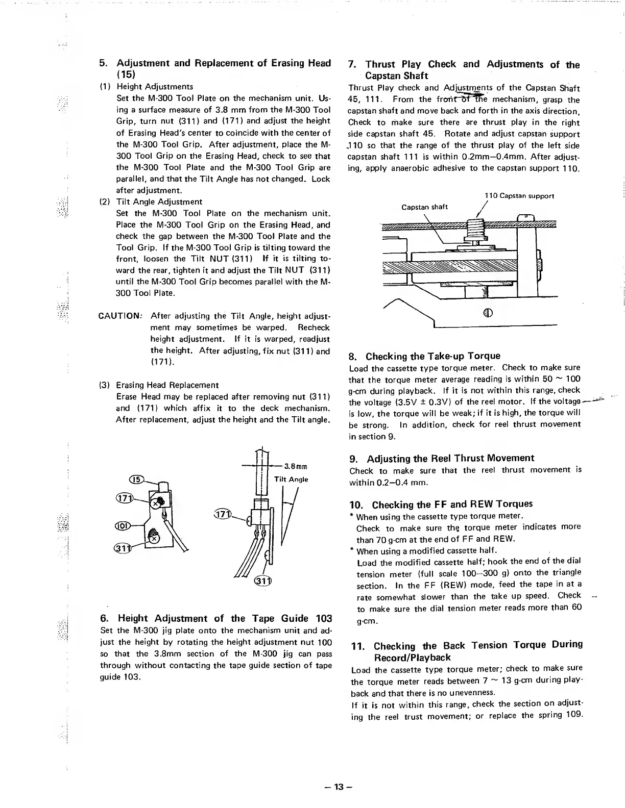
5.
A
djustment
and
Replacement
of
Erasing
Head
(15)
(1)
Height
Adjustments
Set
the
IVI-300
Tool
Plate
on
the
mechanism
unit.
Us¬
ing
a
surface
measure
of
3.8
mm
from
the
M-300
Tool
Grip,
turn
nut
(311)
and
(171)
and
adjust
the
height
of
Erasing
Head's
center
to
coincide
with
the
center
of
the
l\/l-300
Tool
Grip.
After
adjustment,
place
the
M-
300
Tool
Grip
on
the
Erasing
Head,
check
to
see
that
the
M-300
Tool
Plate
and
the
M-300
Tool
Grip
are
parallel,
and
that
the
Tilt
Angle
has
not
changed.
Lock
after
adjustment.
(2)
Tilt
Angle
Adjustment
Set
the
M-300
Tool
Plate
on
the
mechanism
unit.
Place
the
M-300
Tool
Grip
on
the
Erasing
Head,
and
check
the
gap
between
the
M-300
Tool
Plate
and
the
Tool
Grip.
If
the
M-300
Tool
Grip
is
tilting
toward
the
front,
loosen
the
Tilt
NUT
(311)
If
it
is
tilting
to¬
ward
the
rear,
tighten
it
and
adjust
the
Tilt
NUT
(311)
until
the
M-300
Tool
Grip
becomes
parallel
with
the
M-
300
Tool
Plate.
CAUTION;
After
adjusting
the
Tilt
Angle,
height
adjust¬
ment
may
sometimes
be
warped.
Recheck
height
adjustment.
If
it
is
warped,
readjust
the
height.
After
adjusting,
fix
nut
(311)
and
(171).
(3)
Erasing
Head
Replacement
Erase
Head
may
be
replaced
after
removing
nut
(311)
and
(171)
which
affix
it
to
the
deck
mechanism.
After
replacement,
adjust
the
height
and
the
Tilt
angle.
6.
H
eight
Adjustment
of
the
Tape
Guide
103
Set
the
M-300
jig
plate
onto
the
mechanism
unit
and
ad¬
just
the
height
by
rotating
the
height
adjustment
nut
100
so
that
the
3.8mm
section
of
the
M-300
jig
can
pass
through
without
contacting
the
tape
guide
section
of
tape
guide
103.
7.
T
hrust
Play
Check
and
Adjustments
of
the
Capstan
Shaft
Thrust
Play
check
and
Ad
justrnen
ts
of
the
Capstan
Shaft
45,
111.
From
the
frorit"bf
The
mechanism,
grasp
the
capstan
shaft
and
move
back
and
forth
in
the
axis
direction.
Check
to
rhake
sure
there
are
thrust
play
in
the
right
side
capstan
shaft
45.
Rotate
and
adjust
capstan
support
,110
so
that
the
range
of
the
thrust
play
of
the
left
side
capstan
shaft
111
is
within
0.2mm—0.4mm.
After
adjust¬
ing,
apply
anaerobic
adhesive
to
the
capstan
support
110.
110
Capstan
support
8.
Checking
the
Take-up
Torque
Load
the
cassette
type
torque
meter.
Check
to
make
sure
that
the
torque
meter
average
reading
is
within
50
~
100
g-cm
during
playback.
If
it
is
not
within
this
range,
check
the
voltage
(3.5V
±
0.3V)
of
the
reel
motor.
If
the
voltage^-^^
is
low,
the
torque
will
be
weak;
if
it
is
high,
the
torque
will
be
strong.
In
addition,
check
for
reel
thrust
movement
in
section
9,
9.
Adjusting
the
Reel
Thrust
Movement
Check
to
make
sure
that
the
reel
thrust
movement
is
within
0.2—0.4
mm.
10.
Checking
the
FF
and
REW
Torques
*
When
using
the
cassette
type
torque
meter.
Check
to
make
sure
th?
torque
meter
indicates
more
than
70
g-cm
at
the
end
of
FF
and
REW.
*
When
using
a
modified
cassette
half.
Load
the
modified
cassette
half;
hook
the
end
of
the
dial
tension
meter
(full
scale
100—300
g)
onto
the
triangle
section.
In
the
FF
(REW)
mode,
feed
the
tape
in
at
a
rate
somewhat
slower
than
the
take
up
speed.
Check
_
to
make
sure
the
dial
tension
meter
reads
more
than
60
g-cm.
11.
Checking
the
Back
Tension
Torque
During
Record/Playback
Load
the
cassette
type
torque
meter;
check
to
make
sure
the
torque
meter
reads
between
7
~
13
g-cm
during
play¬
back
and
that
there
is
no
unevenness.
If
it
is
not
within
this
range,
check
the
section
on
adjust¬
ing
the
reel
trust
movement;
or
replace
the
spring
109.
-
1
3
-

Table of Contents