
L
Lindsey CortezJul 29, 2025
What to do if CN2 connector voltage check fails on my Denon DSD300 Docking Station?
- BBrittany ChristensenJul 29, 2025
If the CN2 connector voltage check fails, replace the AC adapter.
What to do if CN2 connector voltage check fails on my Denon DSD300 Docking Station?
If the CN2 connector voltage check fails, replace the AC adapter.
Procedure for checking leakage current before returning the set to the customer.
General cautions regarding electric shock, disassembly, parts usage, and servicing.
Identifies critical safety parts and emphasizes using designated replacement parts.
Precautions for battery safety, handling, disposal, and long-term storage conditions.
Important notes regarding schematic diagrams and parts list conventions.
Details audio, clock, wireless LAN, and AC adapter specifications for the DSD300.
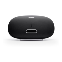
Provides the physical dimensions and weight of the DSD300 speaker dock.
Step-by-step guide for removing the main PWB unit from the DSD300.
Step-by-step guide for disconnecting and removing the CX870 module.
Step-by-step guide for disconnecting and removing the battery module.
Step-by-step guide for removing the charger and amplifier assembly.
Step-by-step guide for removing the touch key PWB unit.
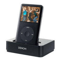
Step-by-step guide for removing the dock connector and OLED assembly.
Step-by-step guide for removing the speaker driver unit.
Resets the unit to default factory settings, clearing data and logs.
Displays system information like product name and software versions.
Shows protection status and allows clearing records for troubleshooting.
Procedure for updating the DPMS firmware on the device.
Displays battery cycle count, total charge, and run times for maintenance.
Guides on system requirements and network setup for firmware updates.
Step-by-step instructions for checking and updating the device firmware.
Important warnings and notes regarding the firmware update process and potential data initialization.
Flowcharts for checking critical voltages (20V, 12V, 3.3V, 1.9V, 1.2V, 5V, 1.1V).
Diagnostic steps for resolving no sound issues from left and right channels.
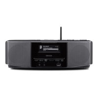
High-level overview of the DSD300's system architecture and component interconnections.
Details the power distribution and voltage regulation within the device.
Provides a visual breakdown of the product's components for assembly and disassembly.
Highlights critical parts requiring manufacturer-recommended replacements for safety and performance.
Lists major semiconductors and their terminal functions, focusing on the MSP430G2202.
| Brand | Denon |
|---|---|
| Model | DSD300 |
| Category | Docking Station |
| Language | English |