Do you have a question about the Denon HEOS Amp HS2 and is the answer not in the manual?
Procedure for performing leakage current checks after servicing.
Identifies important safety parts and the need for designated replacements.
Procedure and remarks for replacing the microprocessor or flash ROM.
Steps for updating firmware via the HEOS app and network.
Instructions for updating firmware using a USB flash drive.
Procedure to write service region settings from USB memory.
Procedure to write service release type settings from USB memory.
Flowchart for firmware burning after core module replacement.
Diagnostic steps for when the unit does not power on.
Steps to diagnose and replace a blown fuse.
Troubleshooting steps for audio output issues on Analog OUT.
Detailed diagram of the switched-mode power supply (SMPS) block.
Circuit schematic for the Digital section 1.
Circuit schematic for the Digital section 2.
Circuit schematic for the Digital section 3.
Circuit schematic for the Digital section 4.
Circuit schematic for the Function & Volume section.
Circuit schematic for the Amplifier section.
Circuit schematic for the Switched-Mode Power Supply (SMPS).
Details and block diagram of the R5F100FCAFP MCU.
Descriptions and assignments for the MCU pins.
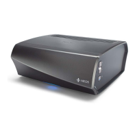
| Amplifier Type | Class D |
|---|---|
| Connectivity | Wi-Fi, Ethernet, Bluetooth |
| Multi-Room Capability | Yes |
| Analogue Input | 1 x RCA |
| Digital Input | 1 x Optical |
| Subwoofer Output | 1 x RCA |
| Frequency Response | 20 Hz - 20 kHz |
| Input Sensitivity | 200mV |
| Signal-to-Noise Ratio | > 100 dB |
| Weight | 2.8 kg |
| Audio Formats Supported | MP3, WMA, AAC, FLAC, ALAC, WAV |
| Streaming Services | Spotify, Tidal, Deezer, Amazon Music |
| Speaker Outputs | 2 x Binding Posts |
| Outputs | Subwoofer, Speaker |
| Power Consumption | 30W (Standby: 0.5W) |