16
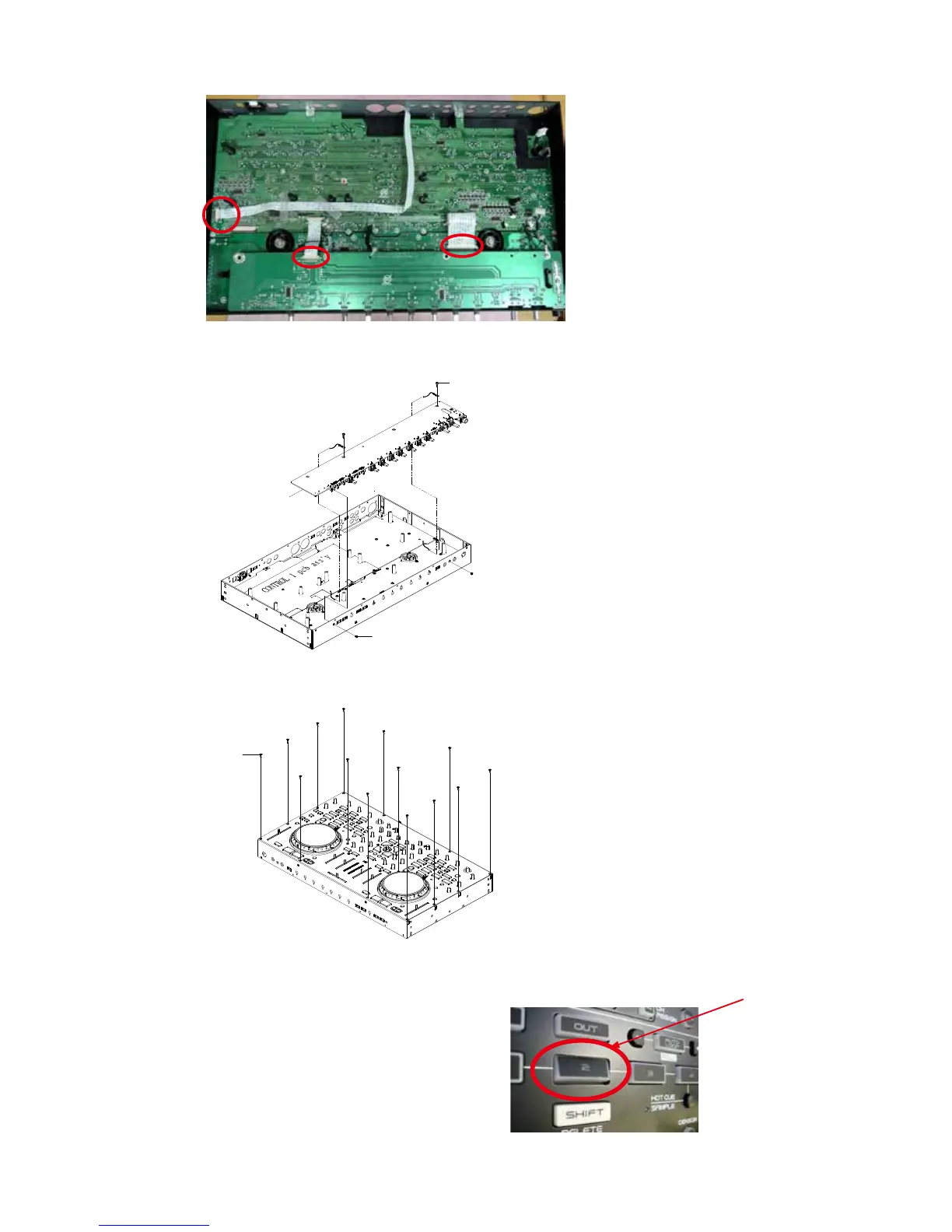
9. Disconnect the FCC cable and connector wire.(follow Figure C).
Shooting direction: C (Bottom side)
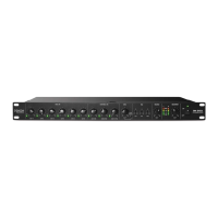
10. Remove the screw*4
Step of screw tightening.(1-4)
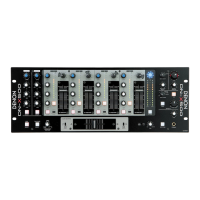
11. Remove the screws *14 from front panel.
Reassemble the front panel by the rst step. Step of screw tightening (1-14).
Caution on assembly of the button.
Adjust and assemble the top panel in the center of the hole.
Press a place other than the center of the button, to conrm that do not catch button on the panel. FAIL
4
3
2
1
Screw*2
FRONT pcb ass'y
Screw*2
1
8
2
3
4
5
6
7
14
13
12
11
10
9
screw*14
Figure C