Explanatory Photos for DISASSEMBLY
• Fortheshootingdirectionofeachphotosusedinthismanual,seethephotobelow.
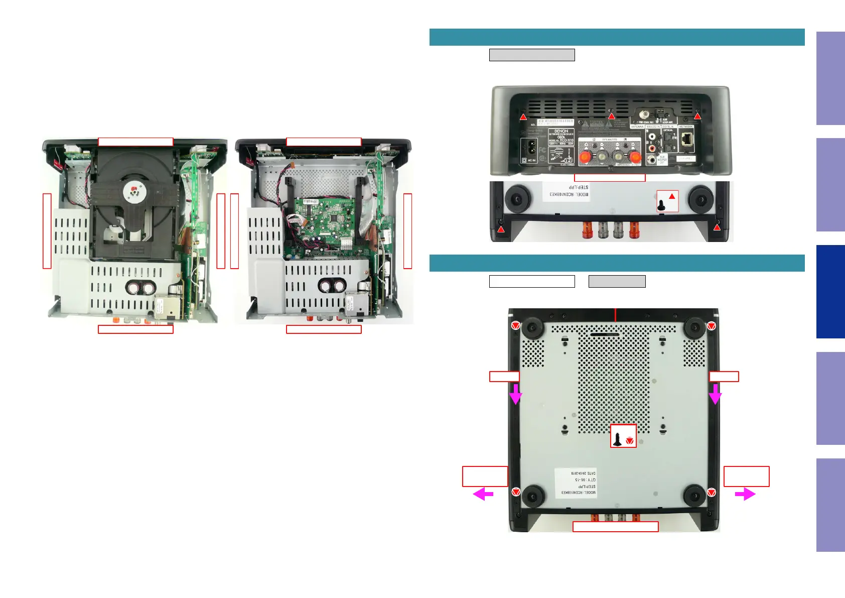
• A, B, C and Dinthephotobelowindicatetheshootingdirectionsofphotos.
• Thephotographswithnoshootingdirectionindicatedweretakenfromthetopoftheunit.
• PhotosofRCD-N10BKE3areusedinthismanual.
The viewpoint of each photograph
(Shootingdirection:X)[Viewfromthetop]
↑Shooting direction: A↑
↓Shooting direction: B↓
↓Shooting direction: D↓
↑Shooting direction: C↑
↑Shooting direction: A↑
↓Shooting direction: B↓
↓Shooting direction: D↓
↑Shooting direction: C↑
Proceeding : REAR MOLD PANEL
(1) Removethescrews.
Proceeding : REAR MOLD PANEL → SIDE PANEL
(1) Removethescrews.
1. REAR MOLD PANEL
View from the bottom
↑Shooting direction: A↑
x5
2. SIDE PANEL ASSY
View from the bottom
STEP1 STEP1
STEP2
TOP SIDE
STEP2
TOP SIDE
x3x4
Before Servicing
This Unit
Electrical Mechanical Repair Information Updating
39

 Loading...


