SPECIAL MODE
Special mode setting button
b
No. 1 : Press and hold the "A" button while inserting the AC plug, then wait for 3-8 seconds. (Power indicator : orange, Eject indicator : white)
b
No. 2 : Press and hold the "A" button while inserting the AC plug, then wait for 3-13 seconds. (Power indicator : white)
b
No. 3 : Press and hold the "A" button while inserting the AC plug, then wait for 3-23 seconds. (Power indicator: white)
b
No. 4: Insert the AC plug while pressing buttons "A" and "B" together, and wait for more than 3 seconds.
b
No. 5, 6: While the power is On, hold down buttons "A" and "B" for at least 3 seconds.
No. Mode Button A Button B Descriptions
1
Selecting the Mode1 for Service-
related
Power -
Service mode information is selected in Service-related selection mode 1.
Service-related modes: No. 1-1 - No. 1-9 (See 1. Selecting the Mode1 for Service-related)
1-1 Version Display Mode
↑ -
The rmware version is shown on the display. (See 1-1. Version Display Mode)
1-2 Product mode
↑ -
Since this mode is only for production/development, the detailed information is not provided.
1-3 Protection history display mode
↑ -
Displays the protection occurrence history. (See 1-3. Protection History Display Mode)
1-4 All Device DPMS Update mode
↑ -
Since this mode is only for production/development, the detailed information is not provided.
1-5 Touch Sensor Check mode
↑ -
Since this mode is only for production/development, the detailed information is not provided.
1-6 Touch Sensor Update mode
↑ -
Update the Touch Sensor rmware. (See 1-6. Touch Sensor Update mode)
1-7 CD Test mode
↑ -
Test the CD mechanism. (See 1-7. CD Test mode)
1-8 Heatrun mode
↑ -
Test of CD mech. (See 1-8. Heat run mode)
1-9 Initialize
↑ -
Initialize the backup data for the MCU and network module. (Settings for the Installer Setup are not initialized.)
(See 1-9. Initialize)
2
Factory Initialization Mode
(Factory Reset)
POWER -
Initialize the backup data only for MCU.
(Settings for the Installer Setup are initialized) (Network function settings are not initialized.)
(See 2. Factory Initialization Mode)
3 Firmware Factory Restore
POWER -
Used when replacing the Network module.
(See 3. Firmware Factory Restore)
4 Tray Lock mode
Open / Close
Disables the OPEN/CLOSE buttons. (See 4. Tray Lock mode)
5 Network Function Reset
POWER BACK
Network module backup data is initialized.
(See 5. Network Function Reset)
6
Selecting the Mode2 for Service-
related
POWER ENTER
Service mode information is selected in Service-related selection mode 2.
Service-related modes: No. 7-1 - No. 7-2 (See 6. Selecting the Mode2 for Service-related)
6-1 LEGO Log Capture Mode
↑ ↑
Acquires the Network Module log. The log is deleted when the Network Module is deleted.
(See 6-1. LEGO Log Capture Mode)
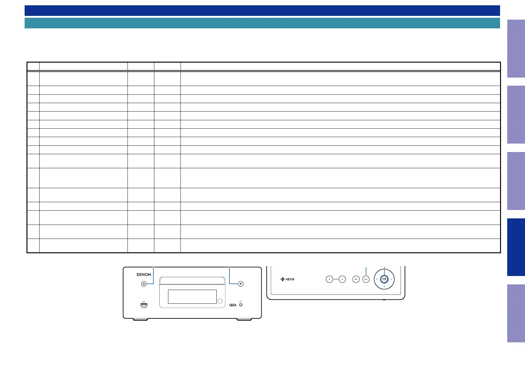
GTop panelH
GFront panelH
BACK
X 5
ENTER
Before Servicing
This Unit
Electrical Mechanical Repair Information Updating
57

 Loading...


