www.desatech.com
116035-01J 15
GROUND FLOOR INSTALLATION
Recommended Applications for Rear Vent
Model (V)CD36T:
• Installation using cabinet surrounds
• Through wall using round or square termi-
nation (up to 24" horizontal pipe)
• Corner installation (Using one 90° elbow
and a maximum of 24" of horizontal pipe)
VENTING INSTALLATION
Continued
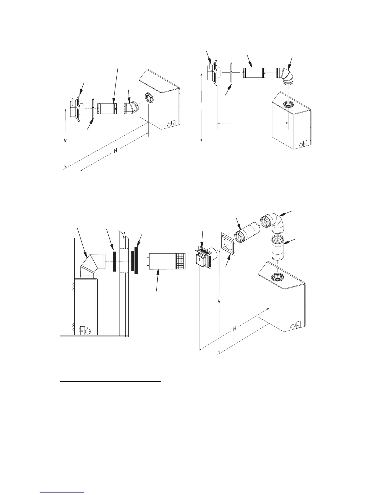
Figure 20 - Horizontal Termination
Conguration Round Termination
(Model (V)CD36T)
Figure 19 - Horizontal Termination
Conguration for Corner Installation
(Model (V)CD36R)
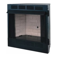
Figure 21 - Horizontal Termination
Conguration For Corner Installation
Using One 90° Elbow (Model (V)CD36T)
Figure 22 - Horizontal Termination
Conguration with Vertical Rise and One
90° Elbow (Model (V)CD36T)
45
1
/
2
" None 26" Max.
57
1
/
4
" Min. 1 ft. 30" Max.
69
1
/
4
" Min. 2 ft. 74" Max.
81
1
/
2
" Min. 3 ft. 98" Max.
94" Min. 4 ft. 122" Max.
106" Min. 5 ft. 146" Max.
159" Min. 9 ft. 20' Max.