www.desatech.com
116035-01J 35
OpERATING OpTIONAL
THERMOSTAT
WARNING: Do not con-
Light the replace as instructed in Lighting
Instructions on page 32. Set wall thermostat
to desired temperature.
This thermostat has been electronically cali-
brated at the factory and requires no adjust-
ment or leveling.
Upon installation, the thermostat must be al-
lowed to stabilize at room temperature for a
minimum of 30 minutes for proper operation.
To turn the replace off, adjust thermostat to
the lowest setting and turn the gas control
knob back to PILOT. The pilot will remain lit.
IMPORTANT: To turn the pilot off, turn the
gas control knob on the heater to the OFF
position.
LIGHTING
INSTRUCTIONS
1. STOP! Read the safety information on
page 32.
2. Turn off all electrical power to replace.
3. Turn wall switch to the OFF position.
4. Open lower louver panel.
5. Turn equipment shutoff valve clockwise
to the OFF position (see Figure
65). Do not force.
6. Wait ve (5) minutes to clear out any gas.
Then smell for gas, including near the
oor. If you smell gas, STOP! Follow “B”
in the safety information on page 32. If
you don’t smell gas go to the next step.
7. Turn equipment shutoff valve counter-
clockwise to the ON position. Do
not force.
8. Close lower louver panel.
9. Turn on all electric power to replace.
10. Turn wall switch to the ON position.
11. Visually locate the pilot. The ignitor should
begin to spark and the main burner should
ignite once ame appears at pilot.
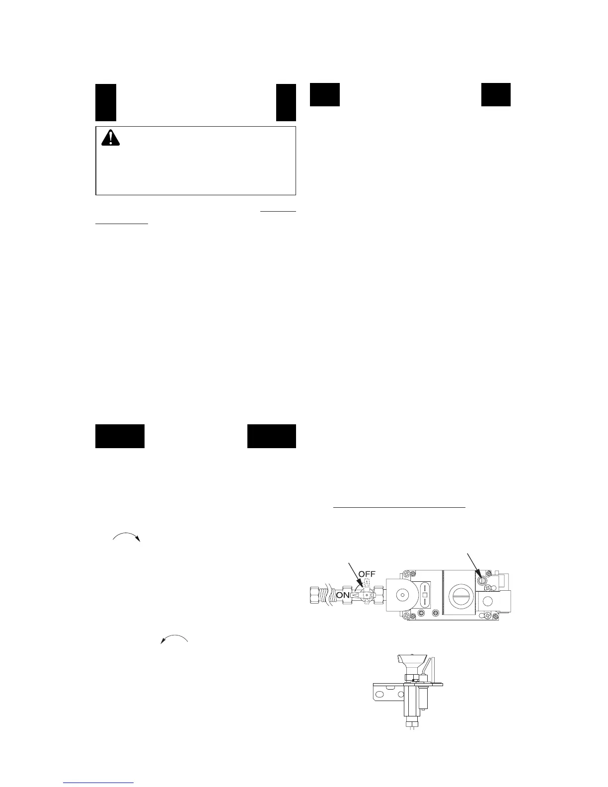
Figure 65 - Turning Equipment Shutoff
Valve to the OFF Position
Equipment
Shutoff Valve
Adjustment
Screw
OPERATION Continued
ELECTRONIC IGNITION MODELS
OpERATING OpTIONAL
Locate blower controls by opening lower
louver panel on replace. Blower controls are
located on right side of switch bracket to left
just inside louver panel.
The BK manual blower and BKT thermostati-
cally-controlled blower have an ON setting
and an OFF setting. The blower will only run
when the switch is in the ON position. In the
OFF position, blower will not operate.
Note for BKT Only: If you are using BKT
blower with optional thermostat (wall mounted
or remote control) for the replace, your re-
place and blower will not turn on and off at the
same time. The replace may run for several
minutes before blower turns on. After heater
modulates to the pilot position, the blower will
continue to run. The blower will shut off after
rebox temperature decreases.
The blower helps distribute heated air from the
replace. Periodically check louvers of rebox
and remove any dust, dirt or other obstruc-
tions that will hinder the ow of air.
• When lighting appliance for the rst time
each season, it may take several at-
tempts before the supply gas can reach
the pilot and main burner.
• If the appliance will not stay lit after
several attempts, follow the instructions
To Turn Off Gas To Appliance, page 36,
and call your service technician or gas
supplier.
Figure 66 - Pilot
MILLIVOLT MODELS