www.desatech.com
116035-01J 37
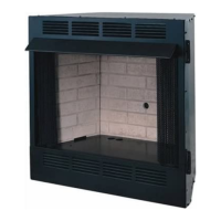
Figure 70 - Typical Flame Pattern
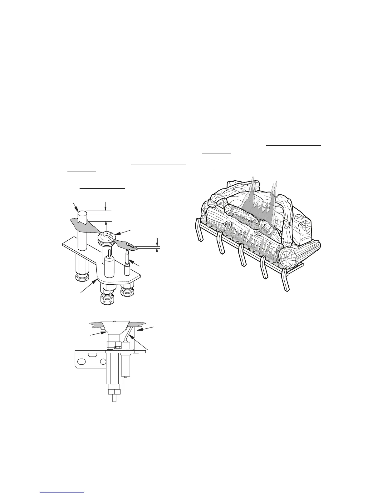
Thermocouple
Thermopile
1/8"
Pilot Burner
Piezo
Ignitor
Figure 68 - Pilot Assembly (Millivolt)
3/8" to 1/2"
INSPECTING BURNERS
Figure 69 - Pilot Assembly (Electronic)
Sensor
Rod
Pilot
Burner
Piezo
Ignitor
Burner ames will be steady; not lifting or oat-
ing. Flame patterns will be different from unit
to unit and will vary depending on installation
type and weather conditions.
If the vent conguration is installed incorrectly,
the ames will lift or "ghost". This can be dan-
gerous. Inspect the ames after installation to
ensure proper installation and performance.
Figure 68 shows a typical ame pattern.
If burner ame pattern differs from that de-
scribed:
• turn replace off (see To Turn Off Gas to
Appliance, page 33 or 36 depending on
model)
• see Cleaning and Maintenance, page 38
Check pilot ame pattern and burner ame
patterns often.
The pilot assembly is factory preset for the
proper ame height. Alterations may have
occurred during shipping and handling. Call
a qualied service person to readjust the pilot
if necessary.
The position and pattern of the pilot ames
in relation to the sensing devices should be
as shown in Figures 68 and 69 depending
on model.
If you pilot assembly does not meet these
requirements:
• turn replace off (see To Turn Off Gas to
Appliance, page 33 or 36 depending on
model)
• see Troubleshooting, page 39