www.desatech.com
116035-01J22
FIREPLACE INSTALLATION
ELECTRICAL SUppLY CONNECTION
CAUTION: Disconnect the
-
-
of local code, with the current
National Electric Code, ANSI/
NFPA 70.
A pre-wired junction box receptacle with
strain relief is provided on the right side of the
cabinet for hard wiring the unit to a 15 Amp,
120VAC, 60Hz grounded branch circuit. If the
installation demands that the electrical supply
be connected from the left side, the entire
receptacle box can be relocated to the left
side by following these instructions:
Note: If you do not need to relocate the junc-
tion box, to connect the electric supply follow
steps 8 through 11 only:
1. Remove 2 screws and outer cover with
strain relief bushing on right side of cabi-
net (see Figure 35).
2. Remove inner retaining screw on junction
box mounting tab.
3. Slide junction box up until screw mounting
tab is lined up to notch in outer cabinet.
4. Swing the junction box out and slip retain-
ing ange out through the slot in outer
cabinet.
5. Remove two screws and outer cover on
the left side of the outer cabinet.
6. Reinsert junction box retaining flange
through slot now on the left side and swing
screw mounting tab back through notch
as before.
7. Slide the junction box down till mounting
tab holes line up and replace the inner
retaining screw.
8. With junction box cover removed, pull the
end of 3-wire Romex supply line through
universal strain relief bushing on cover
(see Figure 35).
9. Strip back the outer Romex to about 4"
and connect black, white and green wires
accordingly using 3 wire nut connectors.
10. Tuck tailing wires into junction box and
replace junction box cover using 2 remain-
ing screws.
11. Tighten down strain adjustment on uni-
versal bushing until Romex sheathing is
secured.
The electrical connection is now complete.
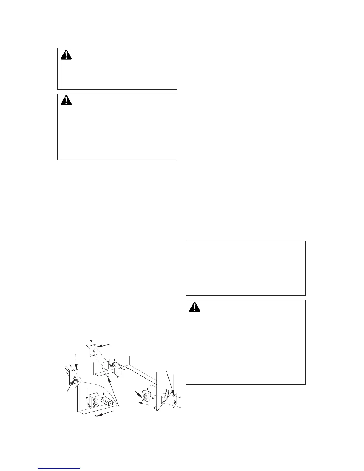
Figure 35 - Relocating Junction Box
Receptacle and Electrical Supply
Connection
J-Box Cover
with Strain
Relief
J-Box
Cover
Romex
Cable
J-Box with
Receptacle
J-Box Cover with
Strain Relief
Screw/Tab
Retainer
ACCESSORIES
-
electrical outlet installed in the
to do this may result in serious
Follow all instructions provided in the blower
accessory kit.
1. Attach power cord to blower motor by
rmly pushing two female terminals at end
of power cord onto two spade terminals on
blower motor (see Figure 36, page 23).