www.desatech.com
116035-01J 25
10. The blower will only run when speed con-
trol knob is in the ON position and thermal
switch senses temperature after replace
begins to heat up. Blower speed can be
adjusted by rotating control knob. To turn
off, turn knob fully counterclockwise until
it clicks off. If blower is ON and has been
running with replace operating, blower
will continue to run for a short time after
replace has been turned off. As thermal
switch cools down, blower shuts down
automatically.
11. Peel off backing paper and stick supplied
wiring diagram decal on rebox bottom
approximately 12" in front of blower (see
Figure 39, page 24).
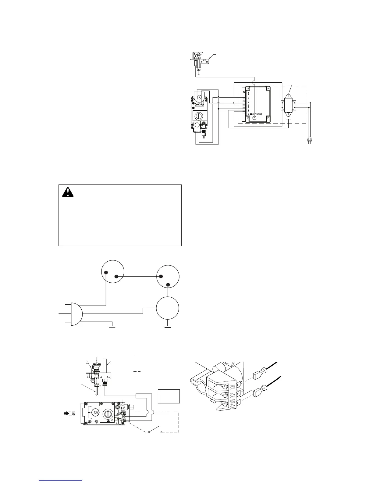
WIRING DIAGRAMS
-
FIREPLACE INSTALLATION
Continued
Figure 41 - Blower Wiring Diagram for
Thermostat-Controlled Models
Figure 42 - Millivolt Ignition Wiring
Diagram
Figure 43 - Electronic Ignition Wiring
Diagram
INSTALLING OpTIONAL WALL
1. Connect one terminal of 25 ft. wire for
wall switch to TPTH terminal on valve.
Connect remaining wire terminal to TH
terminal on valve. Make sure wire termi-
nals are in positions on unit as pictured
in Figure 44. If wires are not connected
as shown switch will not work.
2. Route 25 foot wire through openings
provided on sides of burner system to
a convenient location to mount your
switch.
3. Connect one bare wire end to each termi-
nal of GWMS2 wall switch.
4. Install wall switch and cover in wall.
IMPORTANT: Do not use any other wire than
that provided with the GWMS2 wall switch kit.
Do not exceed 15 feet of distance from valve
connection. Using wire of higher gauge or
turns or exceeding the minimum distance will
increase resistance at control valve causing
unreliable performance of replace controls.
Figure 44 - Connecting Wall Switch to
Control Valve
To Wall
Switch
Accessory