www.desatech.com
116035-01J 7
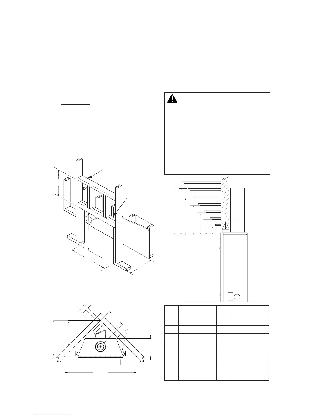
Figure 5 - Framing Clearances for
Installation Against an Exterior Wall
Figure 6 - Framing Clearances for Corner
Installation
PRE-INSTALLATION PREPARATION
Continued
FRAMING AND FINISHING
Figure 5 shows typical framing of this replace.
Figure 6 shows framing for corner installation.
All minimum clearances must be met.
For overall unit dimensions, framing allow-
ances and vent collar locations, see unit
dimensions in Figure 9, page 8.
For available accessories for this replace,
see Accessories on page 52. If you are us-
ing a separate combustible mantel piece,
refer to Figure 7 and Figure 8, page 8 for
proper height and clearances. You can install
noncombustible mantels at any height above
the replace.
Note: Noncombustible mantels may discolor!
14
3
/
4
"
(37.5 cm)
2"x4" Vertical
Double Stud
Ref. Mantel Depth Ref.
Mantel from
Top of Louver
Opening
1 16" (40.6 cm) A 14" (35.6 cm)
2 14" (35.6 cm) A 12" (30.5 cm)
3 12" (30.5 cm) B 10" (25.4 cm)
4 10" (25.4 cm) C 8" (20.3 cm)
5 8" (20.3 cm) D 6" (15.2 cm)
6 4" (10.1 cm) F 4" (10.1 cm)
7 2" (5.1 cm) G 2" (5.1 cm)
Figure 7 - Clearances for Combustible
Mantels
MANTEL CLEARANCES
Figure 7 shows projected mantel depths at
various heights above the top of the louver
opening. Figure 8, page 8, shows the mini-
mum allowable distances from various mantel
components in relation to the both sides of the
replace opening.
-
used and the face are sealed with