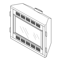
Example 1 shows the minimum allowable
system height and lateral offset for a 60° or
greater inclination. Code species that offsets
at 60° or greater are considered horizontal
and must follow the 75% rule for lateral to
total vertical system height. Codes also al-
lows only one offset in the total system when
at 60° or greater. The total vertical height in
this example represents the minimum height
of 8 feet and therefore the allowable lateral
is 6 feet when the 75% rule applies. If the
lateral length must exceed 75% then the
system must be sized in accordance with the
Category I venting tables.
Example 2 shows a multiple offset each at 45°
of inclination. Multiple offsets are permitted if
they do not exceed 45° of inclination. The total
lengths of the two offsets are not required to
meet the 75% allowable rule.
Example 3 shows a single offset at 45° of
inclination and therefore the lateral length at
10 feet of offset does not have to meet the
75% rule.
In each case the offsets must be supported
and restops must be positioned wherever
the vent must pass through a suboor, ceil-
ing joist or an attic overhang. The vent pipe
must terminate vertically into a listed type vent
cap and extend a sufcient height through
an approved roof ashing, roof jack or a roof
thimble. At all points the listed clearances
must be maintained.
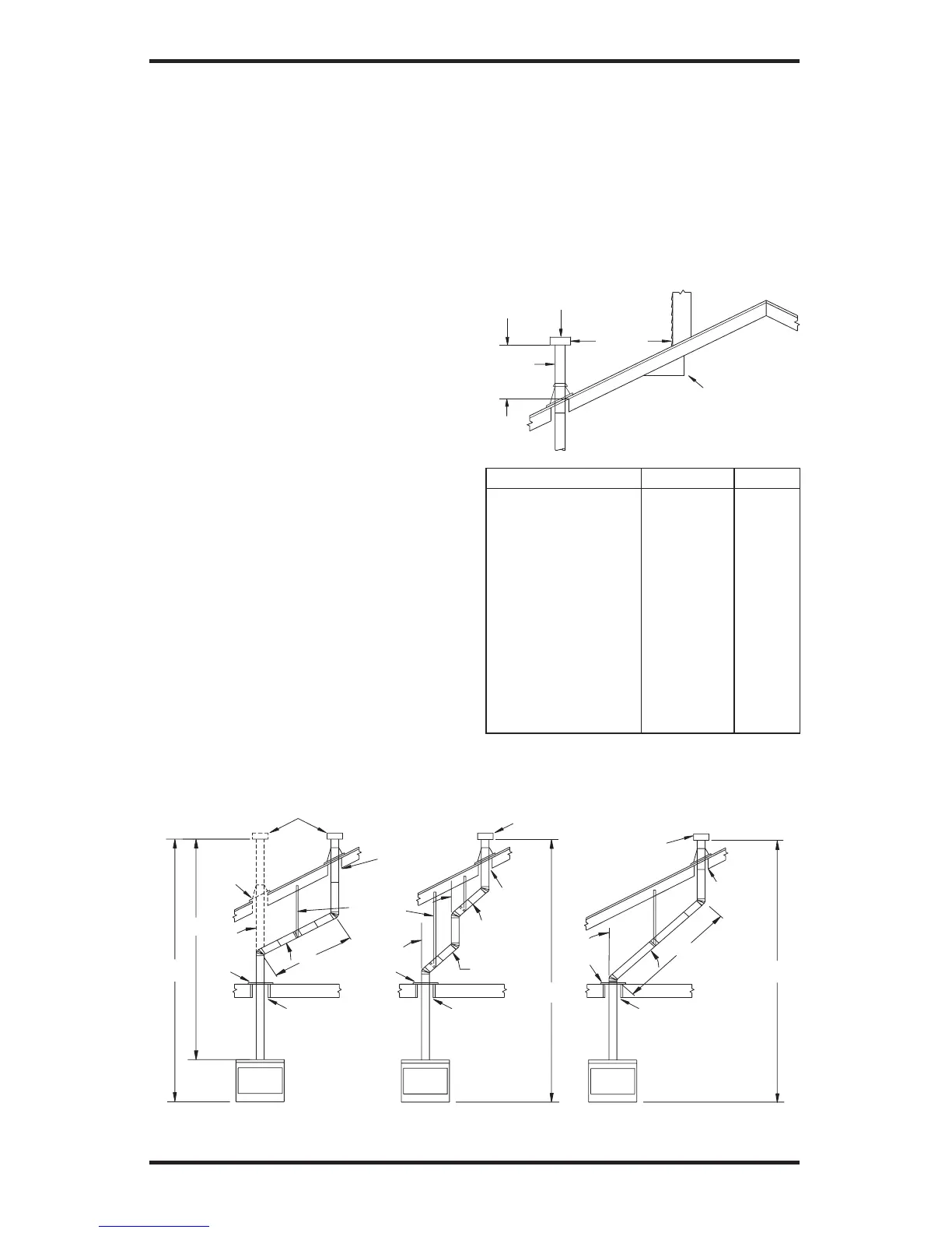
Vent terminations must be located in accor-
dance with height and proximity rules of NFPA
Roof Pitch H(Min.)Ft. m
Flat to 6/12 1.0 0.30
6/12 to 7/12 1.25 0.38
Over 7/12 to 8/12 1.5 0.46
Over 8/12 to 9/12 2.0 0.61
Over 9/12 to 10/12 2.5 0.76
Over 10/12 to 11/12 3.25 0.99
Over 11/12 to 12/12 4.0 1.22
Over 12/12 to 14/12 5.0 1.52
Over 14/12 to 16/12 6.0 1.83
Over 16/12 to 18/12 7.0 2.13
Over 18/12 to 20/12 7.5 2.27
Over 20/12 to 21/12 8.0 2.44
Figure 10 - B-Vent Terminations
VENTING INSTALLATION
Continued
No. 54 or CAN/CSA B149. These rules apply
to vents at 12" diameter or less and require a
minimum height in accordance with the roof
pitch and a minimum of 8 feet distance from a
vertical wall or obstruction (see Figure 10).
If venting horizontally through a side wall be-
comes necessary, a listed thimble approved
for use with B-type vent must be used. Check
with your local codes before venting through
a side wall.