www.desatech.com
108660-01E20
TO TURN OFF GAS
TO APPLIANCE
1. Turnoffwallswitch(ifinstalled).
2. Turn off all electric power to appliance
ifserviceistobeperformed.
3. Fully open glass doors if installed.
4. Removefronthearthbrickandcontrol
access panel.
5. Turn gas control knob clockwise
to “OFF”. Do not force.
6. Replacefrontrefractorybrickaccess
panel.
7. Fully close glass doors if installed.
OPERATING FIREPLACE
Continued
OPTIONAL HAND-HELD
REMOTE OPERATION
Note:Receiverandhand-heldremotecon-
trolkitmustbepurchasedseparately(see
Accessories,page25).Followinstallation
instructionsonpage12ofthismanual.
1. Afterlighting,letpilotameburnfor
aboutoneminute.Turncontrolknobto
ON position. Slide the selector switch
to the REMOTE position. Note: Burner
may light if hand-held remote ON
button was on when selector switch
was last turned off. You can now turn
burner on andoff with hand-held re-
motecontrolunit.
IMPORTANT: Do not leave selector
switch in the REMOTE position when
pilotisnotlit.Thiswilldrainbattery.
IMPORTANT: Be sure to press ON/OFF
buttonsonhand-heldremotecontrol
unit for up to 3 seconds to assure
proper operation.
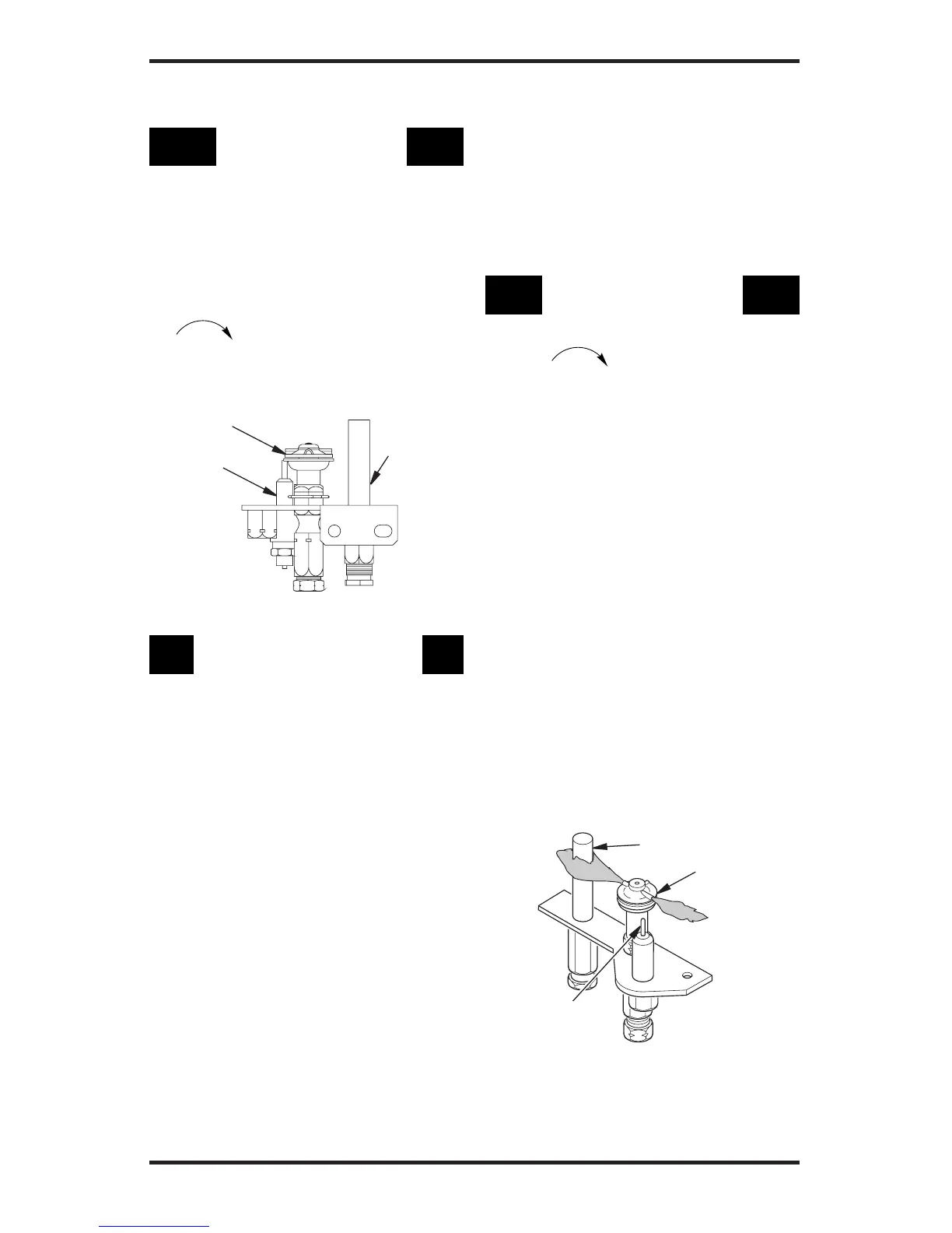
Thermopile
Pilot Burner
Ignitor
Figure 38 - Correct Pilot Flame Pattern
Figure 37 - Pilot
Thermopile
Pilot
Burner
Ignitor
2. PressON/OFFbuttontoturntheburner
on and off. When turning burner off,
pilotwillremainlit.
IMPORTANT:Toturnpilotoff,manually
turn control knob on heater to OFF
position.
3. Toleavepilotlitandshutoffburners
only,turnremotecontrol/wallswitch
(ifinstalled)totheOFFposition.)
TO TURN OFF GAS
TO APPLIANCE
1. Pressinandturncontrolknobclock-
wise to the OFF position.
2. Closeequipmentshutoffvalve
INSPECTING BURNERS
Check pilot ame pattern and burner ame
patterns often.
PILOT ASSEMBLY
The pilot assembly is factory preset for the
proper ame height. Alterations may have
occurred during shipping and handling. The
pilot is located on the back right hand side
of the burner.
The height of thermopile must be 3/8" to 1/2"
above pilot ame. Flame from pilot burner
must extend beyond thermopile.
If your pilot assembly does not meet these
requirements:
• Turn adjustment screw marked pilot clock-
wise to decrease or counterclockwise to
increase ame to proper size (see Figure
36, page 19). Do not remove adjustment
screw.
• see Troubleshooting, page 22