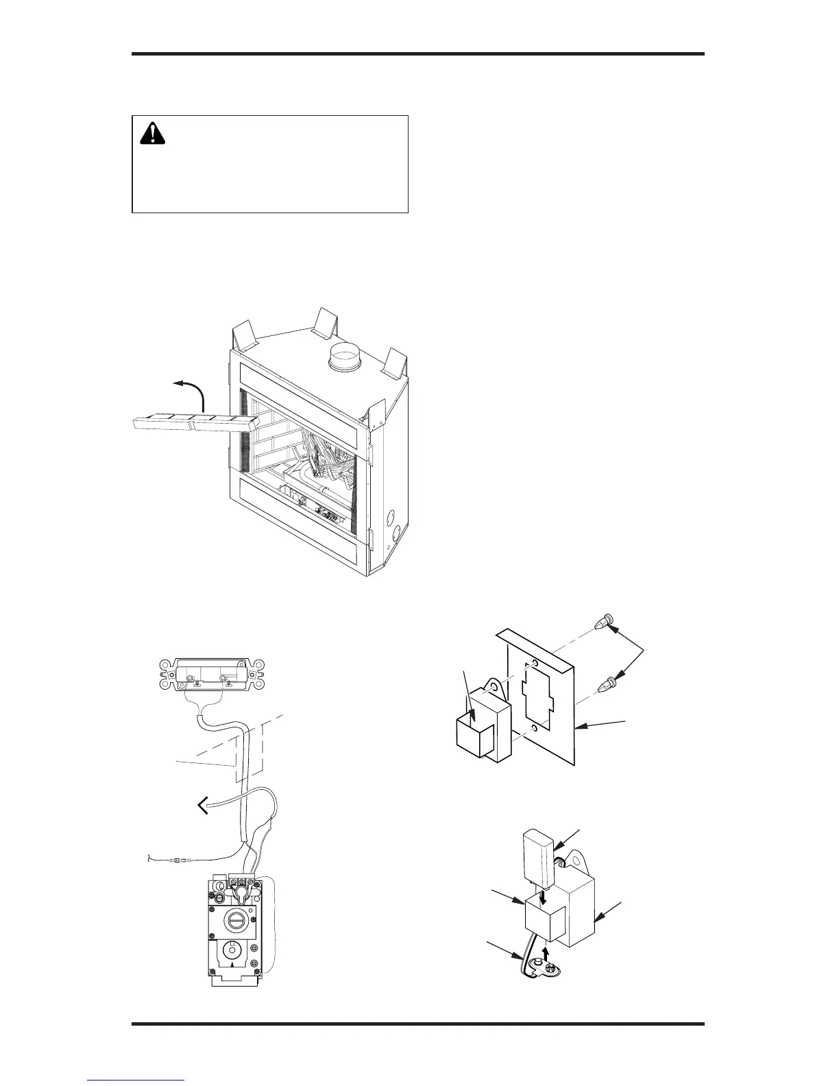
Figure 12 - Removing Front Refractory
Access Panel (P325B/VP325 Model
Shown)
WARNING: Do not wire re-
motewallswitchtomainpower
supply (standard 120V house-
holdcurrent).
3. Locate wall switch in a convenient
location.
4. After wire connections are complete,
replace refractory access panel.
OPTIONAL WIRELESS HAND-HELD
REMOTE CONTROL INSTALLATION
Note: If using optional wireless hand-held
remote control, the wall switch is no longer
operational.
Installing Receiver
1. Remove front refractory access panel
by lifting up and angling out of the re-
box opening (see Figure 12) to expose
controls.
2. Disconnect wall switch wires from TH/TP
terminals on control valve and blade con-
nector on safety circuit wiring (see Figure
13 and Wiring Diagram on page 31).
3. Install remote receiver unit onto mounting
bracket using two plastic mounting clips
(see Figure 14).
4. Connect wires to control circuit. Connect
white wire to terminal marked TH/TP on
control valve. Connect red wire to male
blade connector provided at open end of
safety circuit wiring (see Wiring Diagram,
page 31).
5. Locate battery clip mounted on back of
receiver (see Figure 15).
6. Slide 9-volt battery (not included) through
clip. Note: Only use alkaline battery.
7. Attach terminal wires to battery (see Fig-
ure 15).
8. Replace refractory brick access panel.
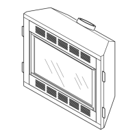
Figure 14 - Installing Remote Receiver
(Shown from Rear of Mounting Bracket)
Receiver
Mounting
Bracket
Plastic
Mounting
Clips
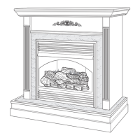
Figure 15 - Installing Battery in Receiver
Battery
Clip
9-Volt Battery
Receiver
Terminal
Wires