Rev 07/04/2015
16
3.4.1 Heater cable features
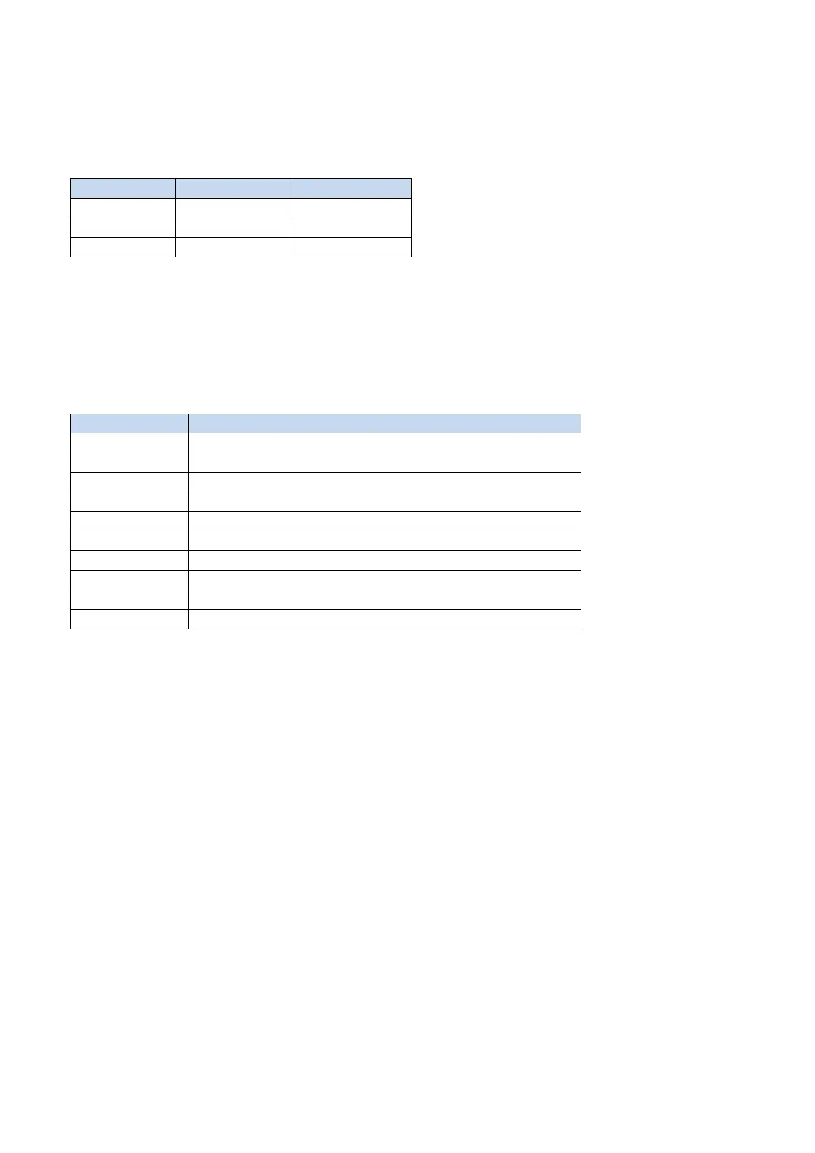
Heater Cable Specifications
Length 2.4 m 2 m (Heated)
Resistance 1.4 kΩ 2.4 kΩ
Current 80 mAmps 90 mAmps
3.5. MAIN BOARD – STANDARD CONTROLLER
Each unit is equipped with a Main Board where the electrical components are
connected. The board has 10 outputs (10 relays) as shown below.
The relays control various components, shown in the table below:
K1 (Load1) COMPRESSOR CONTACTOR COIL
K2 (Load2) PUMP-DOWN VALVE
K3 (Load3) EVAPORATOR FAN MOTOR CONTACTOR COIL
K4 (Load4) DEFROST VALVE
K5 (Load5) UV LAMP
K6 (Load6) HEATED NEEDLE PROBE
K7 (Load7) CONDENSER FAN MOTOR CONTACTOR COIL
K8 (Load8) DOOR FRAME HEATER
K9 (Load9) LIGHT
K10 (Load10) ALLARM
Depending on the unit’s voltage rating, each load is directly connected to either L1 or
Neutral. L2 is switched by the dedicated relay.
3.5.1 Checking Relay Outputs
When a component is not running it may be useful to understand if the related relay output
is working properly. The relays should cut-in and off according to the logic sequences of
the controller. To check an output just disconnect the input Line to the relay and the output
wire (e.g. to check K10 disconnect both wires on 19 and 20 terminals). Ohm out the relay
terminals and check if the contact is closed when the relay is activated. A faulty relay may
remain always opened or become shorted. When this occurs, replace the board.