EasyManua.ls Logo

Desoutter Industrial Tools ESP2-A User Manual

Desoutter Industrial Tools ESP2-A
172 pages
To Next Page IconTo Next Page
Page #1 background imageLoading...
Page #1 background image
www.desouttertools.com
Part no 6159922220
Issue no 05
Date 02/2018
Page 1 / 172
ESP2-A controller
Model Part number
ESP2-A 6159327080
User manual
WARNING
WARNING
Read all safety warnings (including the ones of the separately provided safety instructions n°
6159930690) and all instructions. Failure to follow the warnings and instructions may result in
electric shock, re and/or serious injury.
Save all warnings and instructions for future reference.
10
AVERTISSEMENT
Lire l'ensemble des mises en garde de sécurité (y compris celles sur la notice de sécurité n°
6159930690 fournie à part) ainsi que l'ensemble des consignes. Le non-respect des mises en
garde et des consignes peut entraîner un choc électrique, un incendie ou des blessures graves.
Conserver l'ensemble des mises en garde et consignes pour pouvoir les consulter ultérieurement.
17
ADVERTENCIA
Lea todas las advertencias de seguridad (incluyendo las contenidas en las instrucciones de
seguridad n° 6159930690 suministradas por separado) y las instrucciones. El incumplimiento de
las instrucciones y advertencias de seguridad puede producir descargas eléctricas, incendios y/o
lesiones personales graves.
Guarde todas las instrucciones y advertencias para futuras consultas.
24
WARNUNG
Alle Sicherheitshinweise (einschließlich der separat bereitgestellten Sicherheitsvorschriften Nr.
6159930690) und alle Anweisungen lesen. Eine Nichtbeachtung der Hinweise und Anweisungen
kann zu Stromschlägen, Bränden und/oder schweren Personenschäden führen.
Bewahren Sie alle Warnhinweise und Anweisungen zur künftigen Verwendung auf.
31
AVVERTENZA
Leggere tutti gli avvisi di sicurezza (inclusi quelli indicati sulle istruzioni di sicurezza n.
6159930690 fornite separatamente) e tutte le indicazioni di sicurezza. Il mancato rispetto degli
avvisi e delle istruzioni può provocare scosse elettriche, incendi e/o gravi lesioni.
Conservare tutti gli avvisi e le istruzioni per consultazioni future.
39
ALERTA
Leia todas as instruções e avisos de segurança (inclusive as que são fornecidas separadamente,
n° 6159930690). A falha em seguir os avisos e instruções pode resultar em choque elétrico,
incêndio e/ou lesão grave.
Guarde todos os alertas e instruções para referência futura.
47
Question and Answer IconNeed help?

Do you have a question about the Desoutter Industrial Tools ESP2-A and is the answer not in the manual?

Desoutter Industrial Tools ESP2-A Specifications

General IconGeneral
BrandDesoutter
ModelIndustrial Tools ESP2-A
CategoryController
LanguageEnglish

Summary

General Safety Warnings

Multilingual Safety Instructions

Core safety instructions provided in multiple languages, emphasizing the need to read and follow all warnings.

Additional Safety Warnings

More Multilingual Safety Instructions

Continues essential safety guidance in various languages.

Contact and Resource Information

Official Desoutter Resources

Links to the official Desoutter website for contact, software, documentation, and spare parts.

Technical Data and Specifications

Product Technical Specifications

Detailed technical specifications including voltage, power, weight, and duty cycle for the ESP2-A controller.

Included Accessories

Lists included accessories such as input/output connectors and tool cables with their part numbers.

Installation Guide

Wall Mounting Instructions

Detailed instructions and dimensions for mounting the ESP2-A controller on a wall.

Controller Component Identification

Panel and PCB Layouts

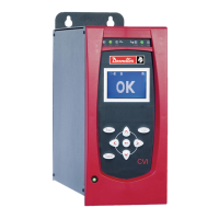
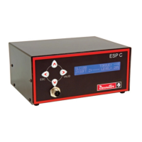
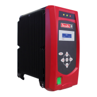
Illustrates the layout of the controller's bottom, front, top panels, and PCB I/O.

Input/Output Wiring and Descriptions

Input and Output Pin Assignments

Detailed descriptions and pin assignments for controller inputs and outputs.

Controller to PLC Wiring Example

Illustrates an example wiring diagram connecting the controller inputs to a PLC.

Controller Output Modes

PLC Interfacing Modes

Explains default contact and transistor controller output modes for PLC interfacing.

Tool and Pset Management

Tool Change and Pset Configuration

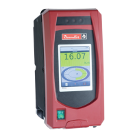
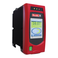
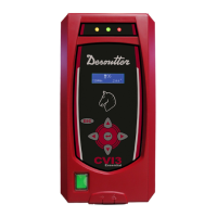
Illustrates controller display and LED feedback for tool changes and Pset selections/errors.

Front and Top Panel Details

Front Panel Item Descriptions

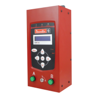
Details each item on the front panel, including LEDs and buttons, with their functions.

Top Panel Connections

Describes the components and connections on the top panel, including earthing.

PCB I/O Configuration

Power Supply Selection

Explains how to select 24VDC or 12VDC output voltage using connector J13.

Output Mode Selection

Details selection of Contact or Transistor output modes via specific connectors.

Detailed Input/Output Descriptions

Input Pin Functions

Detailed descriptions of each input pin and its function for controlling the tool.

Output Pin Functions

Detailed descriptions of each output pin and its signaling behavior.

Controller Configuration and Settings

Tool and Pset Configuration Options

Explains settings for reverse counting, buzzer, and batch counting modes.

Programming and Saving Settings

Guides on how to program, save settings, and select Psets for the controller.

Pset Configuration Details

Pset Status and Description

Explains Pset status indicators and how to enter Pset descriptions.

Pre-run Reverse and Slow Start Phases

Details the programming of "Pre-run reverse" and "Slow start" phases.

Advanced Pset Phases and Troubleshooting

Tightening, Turbo, and Post-run Phases

Describes the Tightening, Turbo, and Post-run reverse phases of operation.

Batch Count and Automatic Learn

Explains batch counting setup and the automatic learning mode.

Troubleshooting Common Errors

Provides solutions for common error codes like E1 (No tool connected/enabled).

Troubleshooting and Error Codes

Detailed Error Code Solutions

Lists and explains solutions for error codes E2 through NS.

Equipment Handling and Maintenance

Assembly, Disassembly, and Pictograms

Guidelines for assembly, disassembly, and understanding pictograms.

Maintenance and Fuse Replacement

Instructions for maintenance, including fuse replacement.

Related product manuals