Do you have a question about the Desoutter CVI3 Function and is the answer not in the manual?
Essential safety guidance for controller and tool usage, emphasizing risk reduction.
Focuses on user safety, especially regarding electrical grounding and avoiding hazards.
Identifies operational risks and limits for tool application.
Guidelines for maintenance by qualified personnel and safety during service.
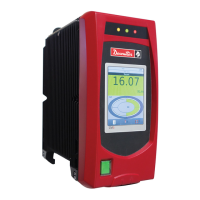
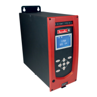
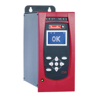
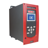
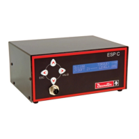
Details the components and functions of the controller's front panel interface.
Explains the meaning of LED indicators for status and actions.
Diagrams and descriptions of ports and connectors on the controller's bottom.
Instructions for setting up and powering the controller.
Step-by-step guide to select the user interface language.
Functionality of navigation icons and keyboard inputs for menu interaction.
Settings for secondary controllers within a workgroup system.
Configuration of IP address, subnet mask, and gateway.
Checking network connectivity by pinging devices.
Information on configuring Fieldbus communication modules.
Setting up custom communication protocols.
Setting and synchronizing the controller's date and time.
Enabling or disabling audible beep feedback.
Activating zoom for detailed viewing of torque, angle, or report.
Shows the status of physical inputs and outputs.
Activating the access manager for parameter protection.
Selecting Psets or Assembly Processes and control modes.
Viewing the most recent tightening operation's results.
Accessing detailed information about tightening reports.
Explanation of symbols for status and operation monitoring.
Defines symbols indicating torque and angle trends.
Viewing the most recent tightening result, including torque and angle.
Navigating and displaying previous tightening results.
Viewing results from run reverse operations.
Essential controller maintenance tasks, including firmware upgrades.
Procedures for ePOD backup, restore, repair, and erasing results.
Viewing and acknowledging user info codes and error messages.
How to check the current controller firmware version.
Diagrams and tables detailing tool connector pinout and cable specifications.
Illustrates RS232 serial communication and barcode reader connections.
Shows how to connect 24V external supplies to digital inputs.
Illustrates how to connect 24V external supplies to digital outputs.
Flowchart illustrating the tightening process via IO signals.
Timing diagrams for IO signals during tightening operations.
Details diode wiring for synchronizing multiple CVI3 controllers.
List of error codes and their resolution procedures.
List of warning codes and their troubleshooting steps.
Comparison of ePOD models, part numbers, and supported features.
| Power Supply | 100-240 V AC |
|---|---|
| Current Consumption | Max. 1.6 A |
| Communication Interface | Ethernet |
| Operating Temperature | 0 to 50 °C |
| Storage Temperature | -20°C to +70°C |