Do you have a question about the Desoutter CVI3 Vision and is the answer not in the manual?
General guidelines for safe tool operation and maintenance.
Precautions to ensure operator safety during tool use.
Identification of potential risks associated with tool operation.
Guidelines for maintaining and servicing the tool.
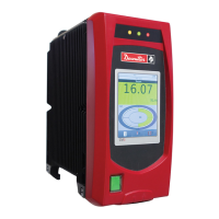
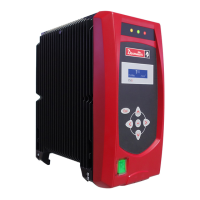
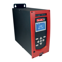
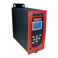
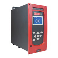
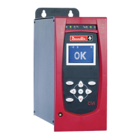
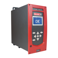
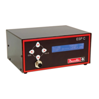
Description of the controller's front panel interface and components.
Explanation of the meaning of different LED indicator colors.
Description of the controller's bottom panel and its connectors.
Items included in the controller kit upon delivery.
Instructions for installing and powering the controller.
Procedure for selecting the controller's display language.
Guide to using icons, digital and text keyboards on the controller.
Configuration options for the controller display settings.
Setting and synchronizing the controller's date and time.
Activating and configuring the controller's access manager.
Setting up the controller as a primary or secondary unit in a workgroup.
Configuring serial ports and USB connections for peripherals.
Configuring network settings for the controller.
Selecting and configuring Fieldbus modules.
Setting up custom communication protocols.
Configuring the CVINet for remote data collection.
Setting up remote display via PC/Windows, Apple, or Android.
Setting up remote display via Apple devices.
Setting up remote display via Android devices.
General settings for the tightening unit, including name and comment.
Selecting the operating mode for the tightening unit.
Defining the source for Pset selection.
Configuring various options for the tightening unit.
Configuring parameters for running the tool in reverse.
Actions to take after a NOK report.
Enabling and configuring curve generation for results.
Managing wireless battery tools connected to the unit.
Customizing display and network settings for wireless tools.
Configuring feature parameters for wireless tools.
Customizing display settings for wireless battery tools.
Configuring network parameters for wireless battery tools.
Configuring settings for Tool 1 (cable connection).
Configuring settings for Tool 51 (wireless battery tool).
Steps to create and add a new Parameter Set (Pset).
Creating a Pset using the expert mode configuration.
Creating a Pset using the simple mode configuration.
General settings for editing a Pset, including torque limits and start torque.
Setting a torque limit to detect fastener damage.
Defining the torque value to declare a Pset as started.
Measuring and controlling the overall angle during tightening.
Measuring and controlling the overall time during tightening.
Advanced Pset settings including external stop and thread direction.
Configuring the Pset to stop upon an external event.
Setting the screw thread direction for tightening.
Configuring and using additional sensors for tightening control.
Defining Pset start and stop conditions like jog and rehit.
Performing checks on the torque transducer.
Setting rejection criteria for trigger loss during tightening.
Enabling the jog function to fit the tool socket.
Configuring the rehit function to detect re-tightened joints.
Enabling socket release for easier tool removal.
Configuring Ergostop for smoother tool stops and reduced reaction.
Selecting and configuring curve recording for tightening results.
Adjusting Pset coefficients for mechanical torsion compensation.
Procedures for copying, pasting, and deleting Psets.
Adding and organizing steps within a Pset.
General parameters common to all tools and steps.
Configuring the tightening step parameters and control strategies.
Setting up torque control with angle monitoring for tightening.
Setting up angle control for assemblies requiring tension accuracy.
Setting up torque or angle control for tension accuracy.
Setting up torque and angle control for tension accuracy.
Configuration for yield point control strategy.
Configuration for seating detection using ePOD2.
Setting up monitoring and options for steps.
Configuring current monitoring for step analysis.
Configuring time monitoring for tightening duration.
General options applicable to individual steps.
Resetting angle measurement at the beginning of a step.
Resetting torque measurement at the beginning of a step.
Resetting prevailing torque offset at the beginning of a step.
Configuring latch threshold for angle measurement.
Configuring motor control for 2-speed and 3-speed tools.
Motor control parameters for 2-speed tools.
Motor control parameters for 3-speed ergospeed tools.
Configuring external stop input to skip steps.
Defining how results are reported upon external stop.
Configuring the loosening function with torque or angle control.
Loosening with torque control and angle monitoring.
Loosening with angle control and torque monitoring.
Motor control settings specifically for loosening operations.
Configuring the prevailing step to check residual torque.
Settings for forward prevailing steps with angle control.
Motor control settings for forward prevailing steps.
Setting parameters for prevailing torque monitoring.
Synchronizing steps across multiple controllers.
Step-by-step guide to creating an Assembly Process.
Procedure to view and manage existing Assembly Processes.
Description of the controller's main monitoring screen.
Changing the display and selecting tools in monitoring view.
Information displayed when a tightening operation is successful.
Information displayed when a tightening operation fails.
Different view options for monitoring data (Simple, Detailed, Curves, Ellipse).
Visual representation of Assembly Process steps and batch status.
Displaying torque and angle values in a simple format.
Simple view for prevailing step measurements.
Displaying detailed tightening results, including NOK information.
Displaying tightening results as curves (Torque vs Angle, etc.).
Displaying results from multiple connected tools.
Displaying results from two connected tools.
Displaying results from all connected tools in a list.
Displaying results for each tool in a workgroup.
Displaying results when using additional transducers.
Monitoring results in consistency mode with additional transducer.
Monitoring results in redundancy mode with additional transducer.
Displaying user information and event messages on the monitoring screen.
Description of the main results screen.
Viewing detailed information for individual tightening results.
Filtering results based on various criteria like torque trend and status.
Displaying and analyzing tightening curves for results.
Maintenance procedures for the controller.
Upgrading the controller firmware using a USB key.
Saving controller data (results, logs, configuration) to a USB key.
Performing advanced diagnostics using a USB key.
Loading and managing CVILOGIX programs.
Configuring physical input/output assignments.
Programming event-driven I/O operations.
Checking network connectivity using the Ping function.
Erasing controller memory data (results, user info, Psets).
Calibrating the controller's touchscreen.
General tool maintenance overview.
Identifying and viewing tool characteristics.
Entering comments for tool identification.
Viewing read-only tool characteristics.
Viewing read-only tool configuration settings.
Monitoring tool operational data.
Viewing transducer calibration data.
Monitoring tool motor temperature limits.
Viewing tool usage counters (partial and total).
Managing and responding to maintenance alarms.
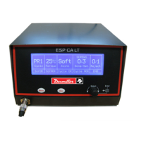
Managing the ePOD backup unit.
Performing backup and restore operations with the ePOD.
Safely ejecting the ePOD from the controller.
Attempting to repair the ePOD and recover data.
Erasing results stored on the ePOD.
Viewing user information codes and event details.
Displaying hardware and firmware version information.
Table defining logical output signals and their conditions.
Table defining logical input signals and their conditions.
User info codes 2-14 and their resolution procedures.
User info codes 32-60 and their resolution procedures.
User info codes 206-233 and their resolution procedures.
User info codes 234-269 and their resolution procedures.
User info codes 300-915 and their resolution procedures.
User info codes 916-924 and their resolution procedures.
Data mapping types and variables for Fieldbus communication.
Defines data types used in Fieldbus communication.
Describes data alignment in Fieldbus communication.
Handling of data saturation in Fieldbus communication.
Fieldbus data types for unsigned integers.
Fieldbus data types for signed integers.
Fieldbus data type for boolean values.
Fieldbus data type for INT16 DEC16 format.
Input variables for Fieldbus communication.
Fieldbus variables related to Pset status.
Fieldbus variables for Assembly Process status.
Fieldbus variables related to socket tray status.
Fieldbus variables for customized protocols.
Output variables for Fieldbus communication.
CVILOGIX inputs for Fieldbus.
Detailed description of the DeviceNet module.
Detailed description of the Ethernet/IP module.
Detailed description of the Profibus module.
Detailed description of the Profinet 1-port module.
Detailed description of the Profinet 2-port module.
Detailed description of the Profinet IRT module.
Detailed description of the CC-Link module.
Diagram and pinout for the tool connector.
Diagram of the CVI II adapter and its components.
RS232 serial port connector pinout.
Digital input connector pinout and example connections.
Digital output connector pinout and example connections.
Flowchart illustrating tightening operation via IO.
Timing chart for tightening operation via IO.
Wiring diagram for synchronizing single-channel controllers.
Wiring diagram for synchronizing TWINCV13 controllers.
Pinout for eBUS connection for accessories.
Diagram illustrating a workgroup setup with controllers and tools.
List of spare parts for CVI3 VISION with part numbers.
Information on controller power consumption and circuit breaker recommendations.
Details on the JVL6-32 residual current circuit breaker.
Comparison of different ePOD models and their functionalities.
| Type | Controller |
|---|---|
| Model | CVI3 Vision |
| Manufacturer | Desoutter |
| Power Supply | 24V DC |
| Storage Temperature | -20°C to 70°C |
| Humidity | 10% to 90% non-condensing |
| Protection Class | IP20 |
| Weight | 1.5 kg |
| Communication Interface | Ethernet |
| Operating Temperature | 0°C to 45°C |