Appendix - Fieldbus_01/2016- 76 -
1.13 - Events in PLC output
All input events described in CVI3 User Manual can be
associated to PLC output in Fieldbus. For each event you can
choose to invert or not the signal. Note that you can associate
up to 4 input events to a unique bit in PLC output. This allows
you to set several events at the same time.
1.14 - Bypass between PLC and IO
For some reasons, you may want to directly control CVI3
inputs/outputs by PLC without any treatment on it.
External input/output bits are dedicated to this usage.
Example: to read a CVI3 physical in PLC memory.
• First, associate a CVI3 input to an “External inputs PLC bit”
in “I/O and accessories” panel:
• Secondly, associate the “external PLC bit” to the PLC
Inputs.
You can now read in PLC the state of CVI3 physical input.
The principle is the same for the outputs.
2 - MODULES DETAILED DESCRIPTION
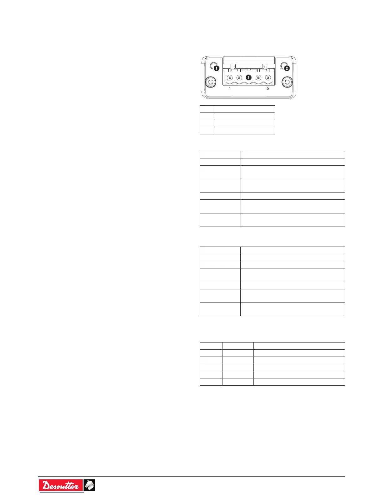
2.1 - DeviceNet
# Item
1 Network Status LED
2 Module Status LED
3 DeviceNet Connector
Network Status
State Indication
Off Not online / No power
Green On-line, one or more connections are
established
Flashing Green
(1 Hz)
On-line, no connections established
Red Critical link failure
Flashing Red
(1 Hz)
One or more connections timed-out
Alternating
Red/Green
Self test
Module Status
State Indication
Off No power
Green Operating in normal condition
Flashing Green
(1 Hz)
Missing or incomplete conguration, device
needs commissioning
Red Unrecoverable Fault(s)
Flashing Red
(1 Hz)
Recoverable Fault(s)
Alternating
Red/Green
Self test
DeviceNet Connector
This connector provides DeviceNet connectivity.
Pin Signal Description
1 V- Negative bus supply voltage *
2 CAN L CAN low bus line
3 SHIELD Cable shield
4 CAN H CAN high bus line
5 V+ Positive bus supply voltage *
* DeviceNet bus power. For more information, refer to
DeviceNet “Technical Specication”.
 Loading...