Appendix - Fieldbus_01/2016 - 77 -
2.2 - Ethernet/IP
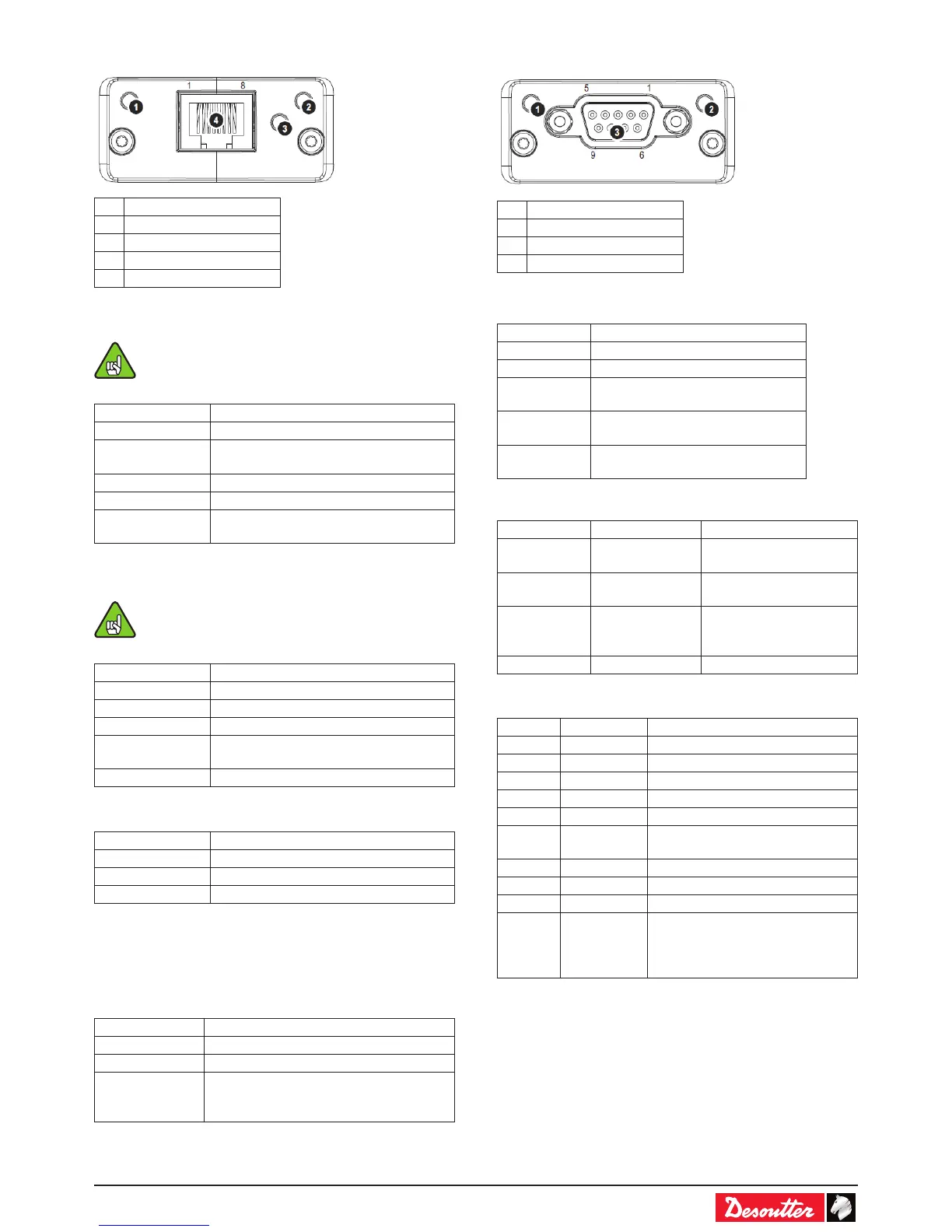
# Item
1 Network Status LED
2 Module Status LED
3 Link/Activity
4 Ethernet Interface
Network Status LED
A test sequence is performed on this LED during
startup.
LED State Description
Off No power or no IP address
Green On-line, one or more connections
established (CIP Class 1 or 3)
Green, ashing On-line, no connections established
Red Duplicate IP address, FATAL error
Red, ashing One or more connections timed out (CIP
Class 1 or 3)
Module Status LED
A test sequence is performed on this LED during
startup.
LED State Description
Off No power
Green Controlled by a Scanner in Run state
Green, ashing Not congured, or Scanner in Idle state
Red Major fault (EXCEPTION-state, FATAL
error etc.)
Red, ashing Recoverable fault(s)
LINK/Activity LED
LED State Description
Off No link, no activity
Green Link established
Green, ickering Activity
Ethernet Interface
The Ethernet interface supports 10/100Mbit, full or half duplex
operation.
CVI3 Ethernet IP module characteristics
Speed 10 and 100Mbits/s supported
Duplex Half and full supported
EDS le release 2.2
WebServer Internal webserver in module allowing
setting connection parameters (IP
address).
2.3 - Probus
# Item
1 Operation Mode
2 Status
3 PROFIBUS Connector
Operation Mode
State Indication
Off Not online / No power
Green On-line, data exchange
Flashing
Green
On-line, clear
Flashing Red
(1 ash)
Parametrization error
Flashing Red
(2 ashes)
PROFIBUS Conguration error
Status
State Indication Comments
Off No power or not
initialized
state = ‘SETUP¨’ or ‘NW
INIT’
Green Initialized module has left the ‘NW
INIT’ state
Flashing
Green
Initialized,
diagnostic
event(s) present
Extended diagnostic bit
is set
Red Exception error state = ‘EXCEPTION’
PROFIBUS Connector (DB9F)
Pin Signal Description
1 - -
2 - -
3 B Line Positive RxD/TxD, RS485 level
4 RTS Request to send
5 GND Bus ground (isolated)
6 +5V Bus
Output *
+5V termination power (isolated,
short-circuit protected)
7 - -
8 A Line Negative RxD/TxD, RS485 level
9 - -
Housing Cable Shield Internally connected to the
protective earth via cable shield
lters according to the PROFIBUS
standard.
* The current drawn from this pin will affect the total power
consumption. To simplify development, the output supplies
up to 60mA when operated in room temperature (20 - 22
degrees Celsius), which is sufcient to power e.g. master
simulators etc. During normal operating conditions (or higher
temperatures), i.e.in an industrial environment, the specied
max. current for this output is 10mA.
 Loading...