6159930310_07_01/2016 - 7 -
2 - GETTING STARTED
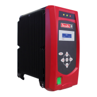
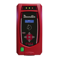
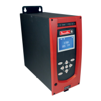
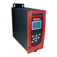
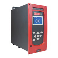
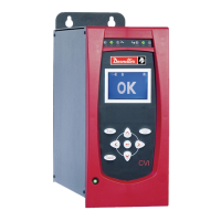
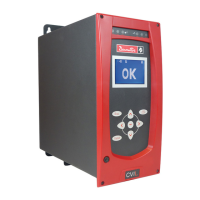
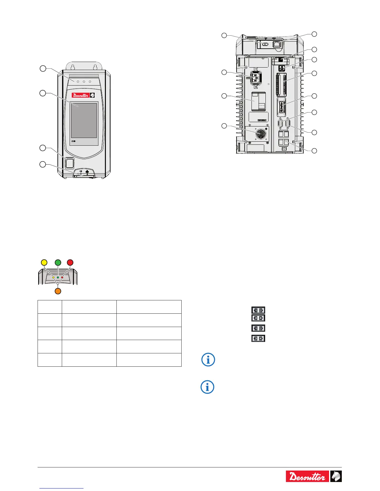
2.1 - Front panel
1
2
3
4
Legend
1 Report LEDs
2 Touchscreen color display
3 On / Off switch
4 Dedicated PC software port + USB port
2.2 - LEDs color code
LED
color
Designation Action
Green Accept report -
Yellow Incomplete rundown Tighten again
Orange Reject report Loosen and tighten again
Red Above High Angle
Remove and replace
fastener.
2.3 - Bottom panel
2
8
9
10
12
3
5
7
11
1
4
6
Legend
1 Ethernet port dedicated only to PC software
2 USB port for data transfer / rmware updating / access
control management
3 ePOD port for controller backup, memory extension,
customer features activation, workgroup conguration.
4 2 USB ports to connect barcode readers
5 Auto-sensing input voltage mains connector
6 2x8 I/O connector dedicated to customer use + 2 quick
stops.
7 Ground Fault Interruptor: earth fault and overcurrent
protection
8 Fieldbus port for plug & play Fieldbus modules
9 eBUS to daisy-chain up to 15 accessories (e.g. socket
tray)
10 RS232 port (2 serial ports) to connect:
Barcode reader / Delta measuring unit
11 8-pin tool connector
12 4 Ethernet ports for 1 or 2 networks:
1 network
• Plug the Ethernet cable
into any port.
2 networks
Ethernet network 1
Ethernet network 2
• Refer to "Appendix - Connections" to get more
information.
• For more information about installing Fieldbus
modules, refer to the " Quick start user manual"
part no. 6159931440 at http://resource-center.
desouttertools.com.
 Loading...