POWER WIRING SIZE AND MAXIMUM LENGTH
1. The OPECL detector must receive 18 Vdc minimum
to operate properly. 24 Vdc minimum is recom-
mended.
2. Always determine voltage drops that will occur to
ensure that 24 Vdc is delivered to the OPECL.
3. Normally, nothing smaller than 18 AWG (0.75 mm
2
)
is recommended by Det-Tronics for OPECL power
cabling.
Wire size requirements are dependent upon power sup-
ply voltage and wire length.
The maximum distance between the OPECL detector
and its power supply is determined by the maximum
allowable voltage drop for the power wiring loop. If the
voltage drop is exceeded, the device will not operate.
To determine the maximum power loop voltage drop,
subtract the minimum operating voltage for the device
(18 Vdc) from the minimum output voltage of the power
supply.
To determine the actual maximum wire length:
1. Divide the maximum allowable voltage drop by the
maximum current draw of the OPECL (0.64 A),
2. Divide by the resistance of the wire (ohms/foot value
available in wire manufacturer’s specification data
sheet),
3. Divide by 2.
For example: Consider an installation using 18 AWG
wiring with a power supply providing 24 Vdc.
Power supply voltage = 24 Vdc,
OPECL minimum operating voltage = 18 Vdc
24 – 18 = 6 Vdc
Maximum Voltage Drop = 6
Maximum Current = 0.64 A
Wire Resistance in Ohms/Foot = 0.006523
6 ÷ 0.64 ÷ 0.006523 ÷ 2 = 718 feet
WIRING PROCEDURE
For systems using conduit, modules must be wired
using a short piece of suitable flexible conduit to allow
optical alignment of the modules. Ensure that all cables
are terminated properly. Open Path Eclipse screw ter-
minal torque range is 3.5–4.4 in.-lbs. (0.4–0.5 N·m).
Cable shield, if used, should be properly terminated. If
not terminated, clip the shield wire off short and insulate
it within the detector housing to prevent the shield wire
from accidentally contacting the detector housing or
any other wire.
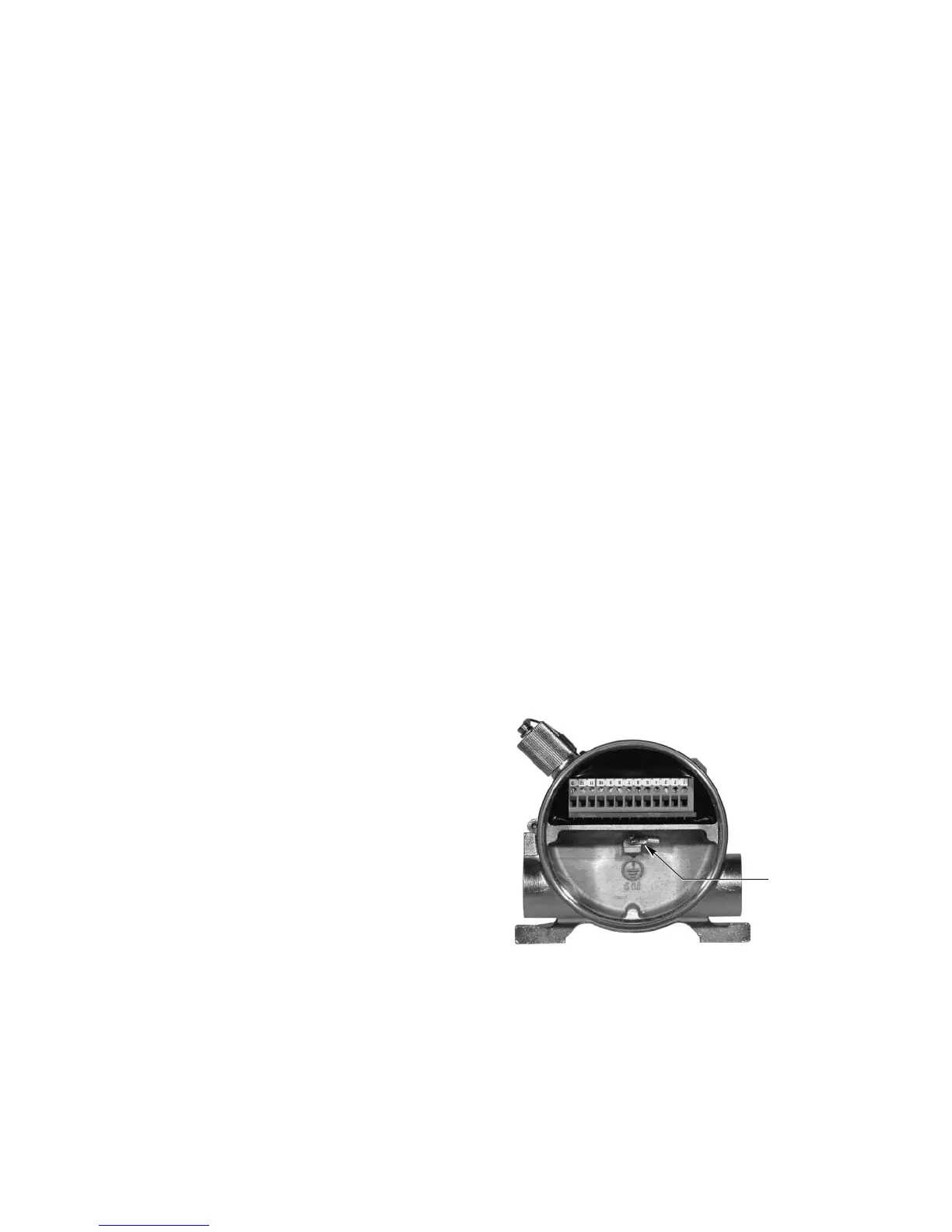
Figure 7 shows the wiring terminal strip located inside
the detector’s integral junction box. Figure 8 shows the
wiring terminal configuration for the OPECL receiver.
Figure 9 shows the wiring terminal configuration for the
OPECL transmitter. (The transmitter requires only oper-
ating power.) Figures 10 through 13 show the 4 to 20
mA output of the OPECL receiver in various wiring
schemes. Figure 14 shows the OPECL wired to a Model
R8471J Controller.
NOTE
The OPECL housing must be electrically connect-
ed to earth ground. A dedicated earth ground lug
is provided for this purpose.
NOTE
For proper HART communication, it is required
that an analog signal loop resistance of 250 to 500
ohms be present at the receiver analog output ter-
minals. See Figure 15 for benchtop test wiring.
11 95-85561.1