MODULE INSTALLATION PROCEDURE
(Must be Completed for both Transmitter and
Receiver Modules)
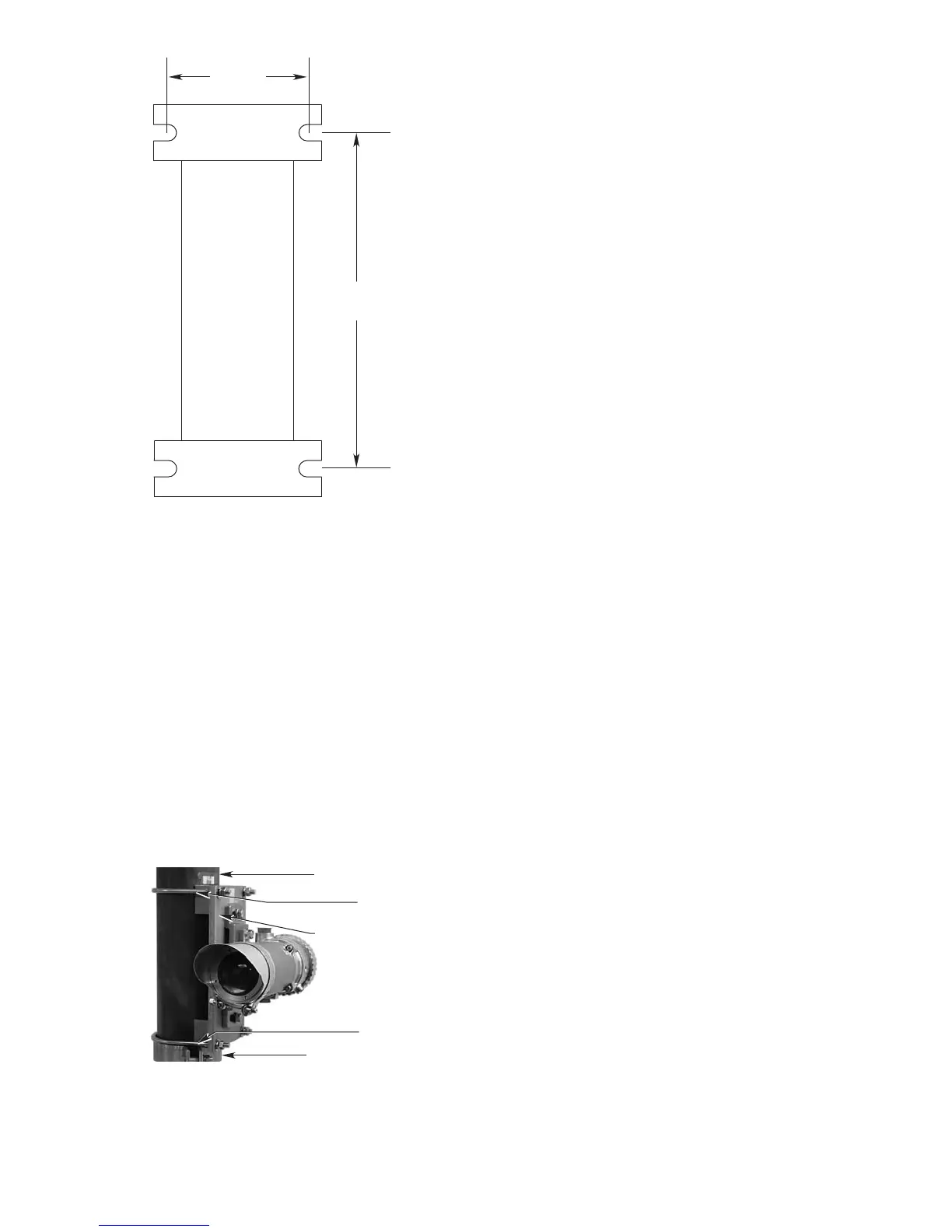
1. Install the Plate Support Collar onto the vertical post
at the desired height. Refer to Figure 6. Ensure that
the plate support collars for both modules are
installed at the same distance above grade/floor ele-
vation to ensure ease of optical alignment later.
Tighten the plate support collar nuts and bolts to
adequately support the entire assembly.
2. Install the Mounting Plate on the vertical post using
(2) U-bolts, (4) washers, and (4) nuts. Tighten the
nuts snugly by hand only at this time so that the
plate is adequately supported but may be rotated if
required.
3. Install the OPECL module onto the Mounting Plate.
Tighten snugly to support the weight of the device.
4. Double check to ensure that the module is ade-
quately supported and is ready for electrical wiring.
IMPORTANT
Do not allow any water or other contaminants to
enter the OPECL electrical termination enclosure if
a delay is expected.
24 VDC POWER SUPPLY REQUIREMENTS
Calculate the total gas detection system power con-
sumption rate in watts from cold start-up. Select a
power supply with adequate capability for the calculat-
ed load. Ensure that the selected power supply pro-
vides regulated and filtered 24 Vdc power for the entire
system. If a back-up power system is required, a float-
type battery charging system is recommended. If an
existing source of 24 Vdc power is being utilized, verify
that system requirements are met.
WIRING CABLE REQUIREMENTS
Always use proper cabling type and diameter for input
power as well as output signal wiring. 14 to 18 AWG
shielded stranded copper wire is recommended.
Always install a properly sized master power fuse or
breaker on the system power circuit.
NOTE
The use of shielded cable in conduit or shielded
armored cable is recommended for optimum
RFI/EMI protection. In applications where the
wiring is installed in conduit, dedicated conduit is
recommended. Avoid low frequency, high voltage,
and non-signaling conductors to prevent nuisance
EMI problems.
CAUTION
The use of proper conduit installation techniques,
breathers, glands, and seals is required to prevent
water ingress and/or maintain the explosion-proof
rating.
10 95-85561.1