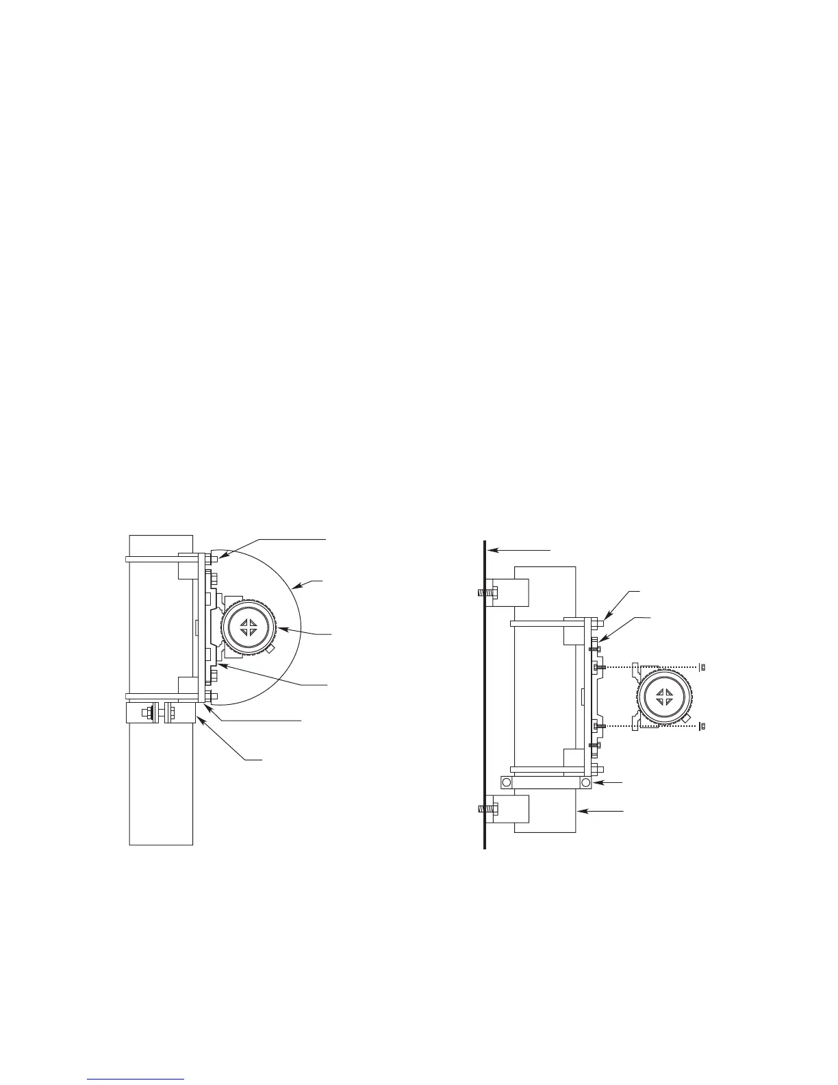
MODULE MOUNTING RECOMMENDATIONS
After optimum system module mounting locations are
identified, the preferred module mounting configuration
must be selected. Each module must be affixed to a
solid, non-vibrating structure capable of supporting a
minimum of 100 lbs (46 kg), located within the system’s
maximum rated separation distance. Module mounting
options include:
•A vertical post with a nominal outside diameter of 4.5”
(11.43 cm). Acceptable outside diameter range is 4.0
to 5.0 inches. Ensure that each post is capable of
supporting a minimum of 50 lbs (23 kg). See Figure 3.
• For flat surface mounting, the OPECL flat surface
mount adapter is available. Ensure that the flat sur-
face is capable of supporting a minimum of 100 lbs
(46 kg). See Figure 4. For mounting hole pattern,
refer to Figure 5.
In all cases, the maximum movement of the supporting
structure under all anticipated operating conditions
must be no more than ±0.5 degrees. When using a ver-
tical post, the post should be absolutely stable and with-
out vibration. Generally, when the post is set into the
ground, the portion below grade should be set in con-
crete at least 1 meter deep.
When using the flat surface mounting adapter, ensure
that the two vertical mounting surface planes are
aligned sufficiently to enable proper module alignment.
It is possible that some existing flat surfaces may not
allow proper system alignment using the OPECL mount-
ing and alignment harware.
System modules are shipped disassembled from the
mounting hardware. Before proceeding with module
installation, ensure that all required module installation
components are present, including:
2 OPECL modules,
2 module mounting brackets,
2 pan-tilt plates,
4 U-bolts complete with
8 washers and nuts, and
2 plate support collars.
For flat surface mounting, two OPECL flat surface mount
adapters (ordered separately) must be installed prior to
starting the module installation procedure.
9 95-85561.1