STARTUP
When the OPECL is installed and wired as described in
the “Installation” section, it is ready for commissioning.
If the application requires that specific changes be
made to the factory settings, HART communication will
be required.
NOTE
Ensure that alarm devices are bypassed during
commissioning.
ALIGNMENT
OVERVIEW
The OPECL modules must be properly aligned before
normal operation can be attained. There are two align-
ment procedure options:
1. Basic Alignment Procedure. This option requires
the OPECL alignment kit, but does not require a
handheld HART communicator.
2. Full Alignment Procedure. This option requires the
OPECL alignment kit and a handheld HART commu-
nicator with the OPECL device descriptor (DD) soft-
ware menu. The full alignment procedure is recom-
mended whenever maximum optical signal strength
is required at the receiver.
BASIC ALIGNMENT PROCEDURE
Equipment Required
1. Properly installed and powered OPECL system
(transmitter and receiver). Easy access to both
modules is highly recommended.
2. OPECL Alignment Kit (PN 007726-001). Kit includes
a battery powered laser, a laser holder, alignment
target and target holder.
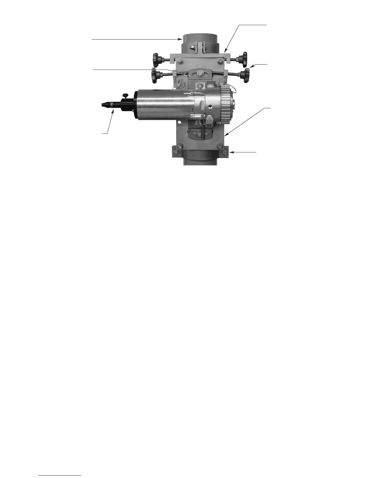
3. Alignment Adjuster Kit (PN 007745-001). Optional
kit includes a battery powered laser, a laser holder,
alignment target and target holder, and removable
vertical and horizontal adjusters. Recommended for
maximum ease in achieving proper alignment. See
Figure 16.
4. Calibration magnet.
Ensure that system power is turned off and metal visors
are slid to the rear to prevent damage, then complete
the following steps:
1. Ensure that both system modules are properly
installed on their respective mounting plate/post
assemblies at a separation distance within the spec-
ified range, and are correctly wired.
14 95-85561.1