240 Operators Manual
Model 240 Operator Manual Rev. 1.8 Page 7 of 29
Ribbon Cable to LCD
Ribbon Cable to
Mother Board
Ni-Cad
Battery
AUXAUX
RS-485 Input for
Gas Sensor
SW1 - Options
4 - Password Protection
3 - Not Used
2 - 600/700 Series Sensors or
Mod 10 Controlers
1 - Analog/Serial
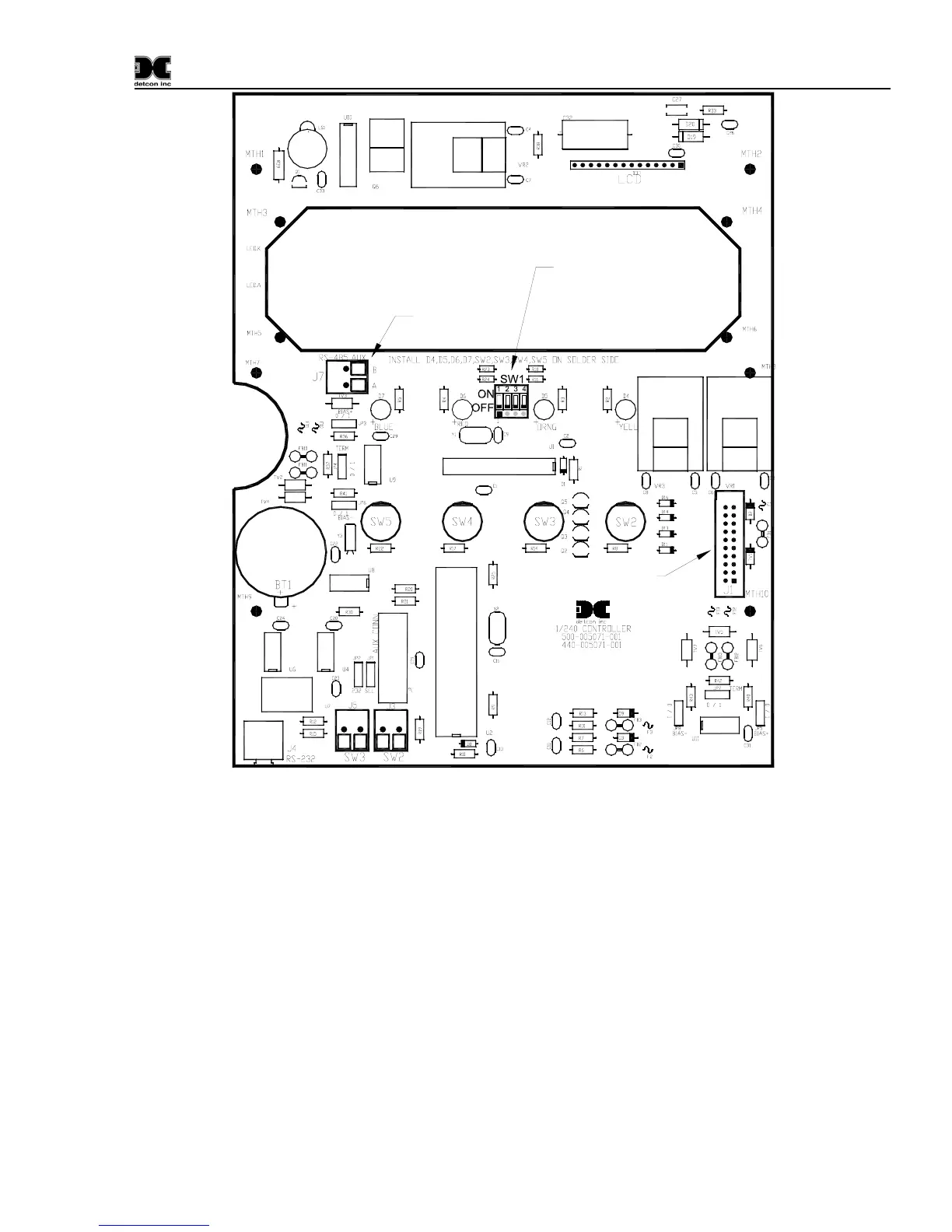
Figure 5 Control Board Layout
4.2.4 Serial Input Gas Sensors
When connecting serial input gas sensors such as the Detcon 600 Series, terminate the 3 conductors from
the serial cable in the following manner. Terminate A and B on the Control PCB at connector J7 shown in
Figure 5. If applicable, the shield wire can be terminated on the Mother Board at JP1 the RS-485 Jumper
labeled ‘SHLD TO GND’ (refer to
Figure 4).
Note: Serial sensor polling requires switch SW1-1 on the Control PCB to be in the “ON” position. If
polling 600 or 700 Series Sensors, SW1-2 must be in the “OFF” position. If polling Mod 10 Controllers,
SW1-2 must be in the “ON” position (See
Figure 5).
NOTE: If VDC power for the Detcon Series 600 sensor is not available at the sensor location, then it can
be provided via the + and – pins of channels 1 and 2 on the motherboard. The RS-485 wiring should be a 2
conductor, shielded twisted pair (Belden P/N 9841 is recommended).