240 Operators Manual
Model 240 Operator Manual Rev. 1.8 Page 5 of 29
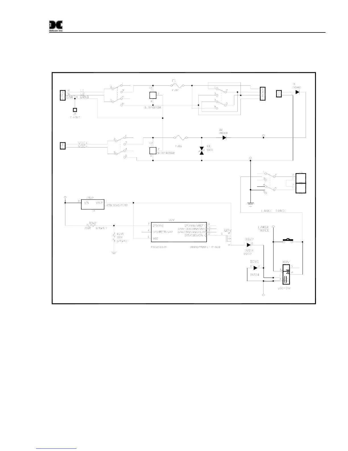
4.2.2 DC Power
For optional DC power input, connect 11.5-30VDC to the terminals at J8, labeled “DC IN” in
Figure 3 and
Figure 4. This input can be used for primary power or back-up power in the event of a VAC power failure.
115VAC/220VAC
External
VDC
Input
VDC ON/OFF
VIN
MOTHER BOARD POWER INPUT
External
VAC
Input
J8
+
-
J2
SW4
SW1
VAC ON/OFF
F2
BATTERY
RESTORE
VSS
VIN
SW3
BATTERY
ON/OFF
SWOV
BATT2
BATT1
DC POWER
SUPPLY
TO
FROM
VSS
VIN
SW2
PS1
PS2
Figure 3 Power Input Schematic
4.2.3 Analog 4-20 mA Sensor Inputs
Connect 4-20mA type gas sensors to the motherboard at the terminals labeled “CH 1” and “CH 2” (J15,
J16, respectively) in
Figure 4. These connections are labeled (+, -, mA). For a 3-wire gas sensor connect
to the “+”, “-”, and “mA” terminations. For a 2-wire sensor connect to the “+” and “mA” terminations,
refer to the Operators Manual for the gas sensor that is being connected.
Note: Analog sensor polling requires switch SW1-1 on the Control PCB to be set in the “OFF” position.
(See
Figure 5)