240 Operators Manual
Model 240 Operator Manual Rev. 1.8 Page 4 of 29
4. Installation
4.1 Mounting and Cable Penetrations
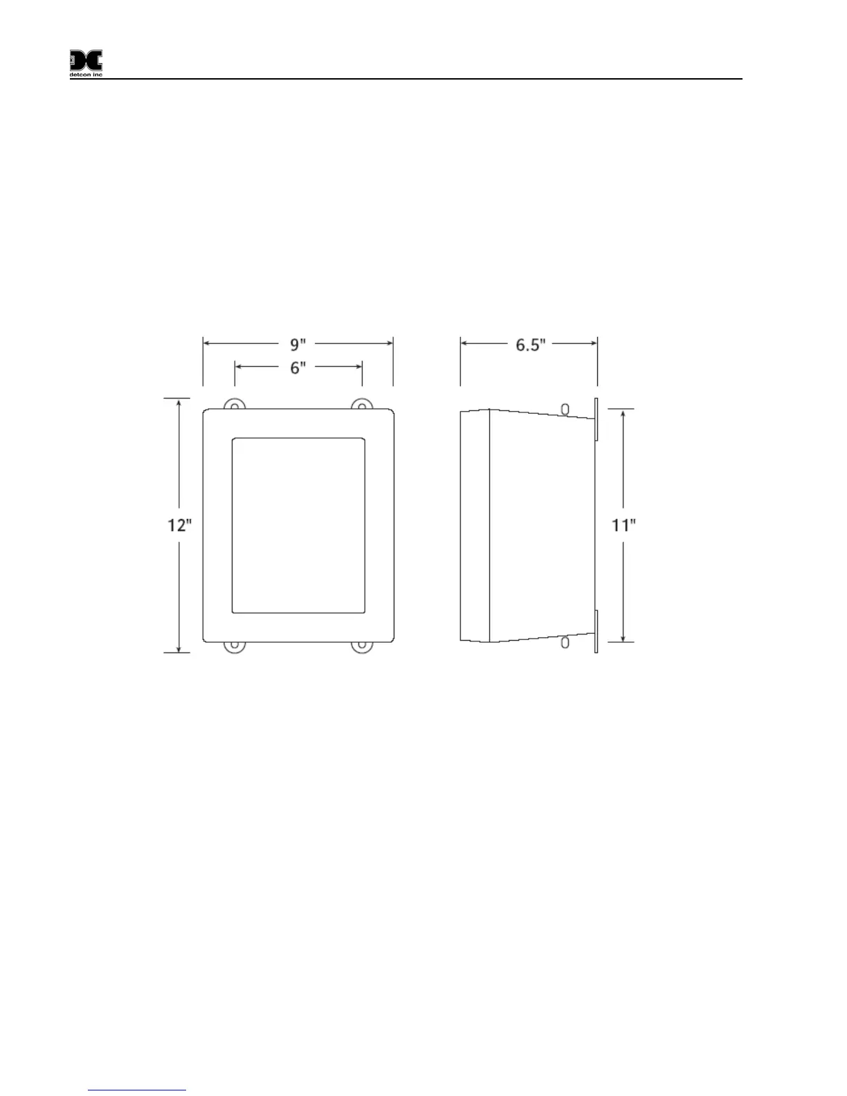
Securely mount the Model 240 N4X enclosure per the mounting dimensions provided in
Figure 2.
Provide for suitable conduit/cable entries in the bottom of the enclosure. Keep AC power separate from
DC signals in conduit connections and runs.
Mounting Holes 5/16 Dia.
Figure 2 Dimensional View of Enclosure
4.2 Power and I/O Connections
Power and I/O connections are made on the Motherboard PCB, mounted inside on the back of the
enclosure. Plug-in male connector terminal blocks are provided for input wire terminations. This
connector style provides for quick disconnect convenience during replacement or servicing. (Refer to
Figure 4)
The connections for serial polling of gas sensors and RS-232 PC downloading activities are located at J7 on
the Controller PCB. (Refer to
Figure 5)
4.2.1 AC Power
Connect the 115 or 230VAC input wiring to the terminals at J2, labeled “AC IN” in
Figure 3 and Figure 4.