32
8.6- OPTION SWITCH SETTINGS – 2 STAGE ECM
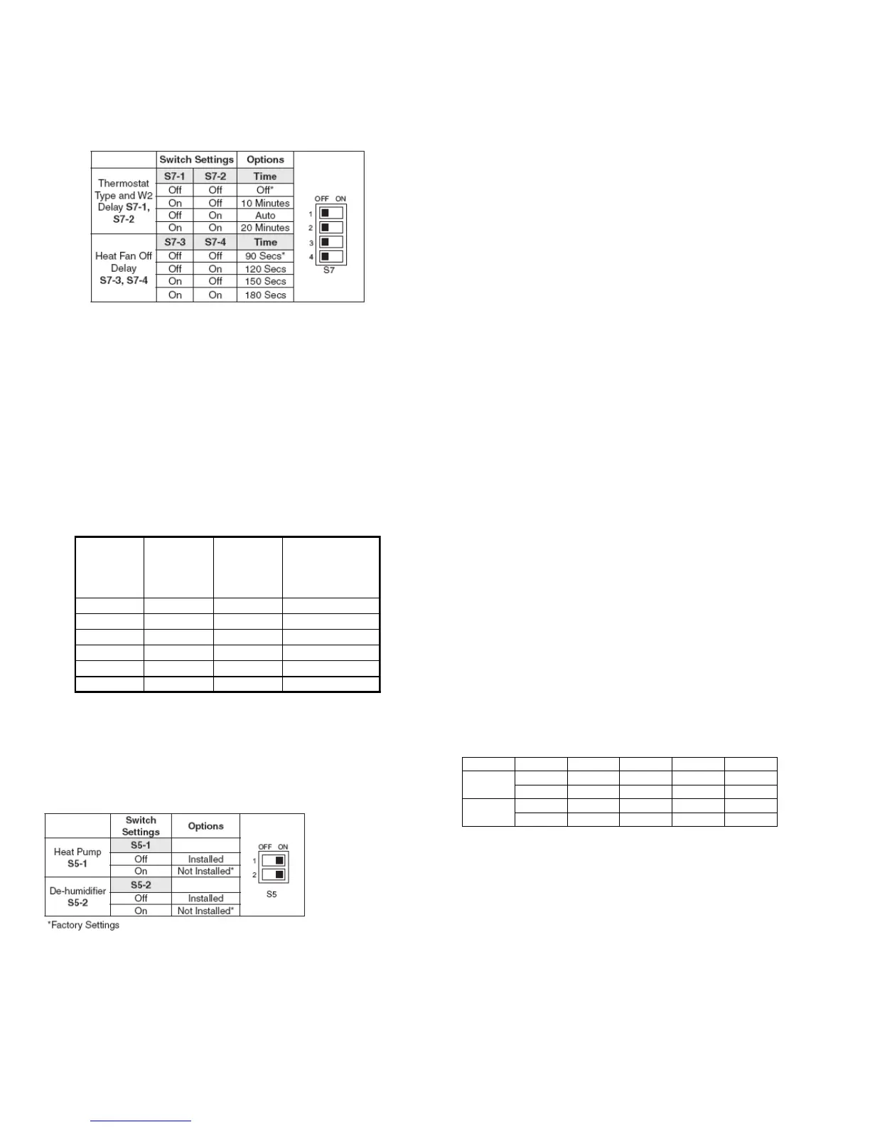
8.6.1- Thermostat type and heat-fan-off delay
Table 19: DIP Switches
8.6.2- Multi-stage thermostat set-up, factory default
DIP switches S7-1 and S7-2 (see table above) are set to the “Off” position
from the factory for use with a multi-stage thermostat. This allows the
thermostat to control staging between low and high fire.
8.6.3- Single stage thermostat set-up, module controls
staging
DIP switches, S7-1 and S7-2 (see table above) configure for a single stage
thermostat. Options include a 10 minutes delay on second stage, 20
minutes delay on second stage or an Auto setting allowing the module to
calculate the time delay for second stage based on average demand. The
“Average Calculated Duty Cycle” table shows how the module calculates
staging based on demand.
Table 20: Duty cycle
8.6.4- Heat fan off delay timing
DIP switches S7-3 and S7-4 (see table above) configure the number of
seconds the blower will run after the call for heat ends. Factory default is
90 seconds.Heat pump and de-humidification
Table 21: DIP Switches
Heat pump systems
DIP switch S5-1 (see table above) is set to “On” from the factory for use
with conventional (non-Heat Pump systems). For heat pump systems
move the S5-1 DIP switch to the “Off” position. This will continuously
output an O signal to the motor whenever there is Y signal and run the
circulator blower at a constant speed when the pump is operating.
8.6.5- De-humidification connection
DIP switch S5-2 (see table above) is set to “On” from the factory for
systems that do not have a dehumidification terminal connection from the
thermostat. For systems using a thermostat that provides a De-
Humidification option move DIP switch S5-2 to “Off”.
8.6.6- Normal operation – heat on
When the thermostat calls for heat the module verifies the pressure
switches are open and energizes the inducer (high speed) and optional
humidifier contacts. When the low pressure switch contacts close a 15
second pre-purge begins. After 15 seconds the inducer switches to low
speed and the 120 VAC igniter is energized. The igniter warms up for 17
seconds and the gas valve is energized on low fire. Flame must be
detected within 4 seconds. If flame is detected, a 45 seconds heat, fan on
time delay begins. This allows the heat exchanger to warm up before
energizing the circulator on low speed and (optional) Electronic Air
Cleaner contact. When the thermostat (or module) initiates second stage
the inducer is energized at high speed.
This closes the second stage inducer pressure switch then energizes the
second stage on the gas valve and then the high heat circulator speed.
8.6.7- Normal operation – heat off
When the thermostat satisfies for second stage, the control will switch high
speed inducer and high fire gas valve to low speed inducer and low fire
gas valve. After the 30 seconds high heat fan delay the circulator will drop
to low speed. When the thermostat satisfies for first stage the gas valve
de-energizes and the inducer will run low speed for a 15 seconds post-
purge. The circulator runs until the heat off delay ends.
Note: If the module is configured for a single stage thermostat and
running on second stage when the call for heat ends, the
circulator will drop to low speed after 30 seconds and continue
until the heat off delay ends.
8.6.8- Cool mode
In a typical system, a call for cool is initiated by closing Y and G. This
energizes the compressor and the electronic air cleaner (optional). The
electronic air cleaner and the G and (Y or Ylo outputs to the Circulator
motor will energize after the 5 seconds cool on delay period. After the
thermostat is satisfied, the compressor is de-energized and the control
starts a 60 seconds cool circulator speed off delay. After 60 seconds the
circulator is de-energized.
8.6.9- Adjust cooling airflow – dipswitch S3-1 and S3-2
The ECM blower can be adjusted for a range of airflow for Low Speed or
High Speed cooling.Refer to CFM tables in Annexe for the relation
between airflow, external static pressure and dipswitch setting. .
Table 22 : Dipswitch setting for airflow selection
8.6.10- Manual fan on mode
If the thermostat fan switch is moved to the “ON” position, the electronic
air cleaner (optional) and the G circulator output to the circulator motor will
be energized. When the fan switch is returned to the AUTO position, the
G circulator output and the electronic air cleaner are de-energized.
Average
calculated
Duty Cycle
% Equals
38 50 10 minutes Light to Average
62 75 5 minutes Average to Heavy
75 88 3 minutes Heavy light





 To Next Page