9
Be provided ample space for servicing and cleaning. Always
comply with minimum fire protection clearances shown in Table 1
Minimum clearance to combustible material
for all units or on the furnace rating label.
Table 1 Minimum clearance to combustible material
for all units
Required for service (front)
All sides of supply plenum
*See local buildings codes.
Table 2 Loose parts list
Screw TEKS HEX WSH #8-18 x ½
2" PVC pipe (Length = 1.5")
Clear PVC tube 5/8" ID x 24"
Clear PVC tube 1/2" ID x 24"
The following types of furnace installations may require OUTDOOR AIR for
combustion due to chemical exposures:
Commercial buildings
Buildings with indoor pools
Laundry rooms
Hobby or craft rooms, and
Chemical storage areas
If air is exposed to the following substances, it should not be used for
combustion air and outdoor air may be required for combustion:
Permanent wave solutions
Chlorinated waxes and cleaners
Chlorine based swimming pool chemicals
Water softening chemicals
De-icing salts or chemicals
Carbon tetrachloride Halogen type refrigerants
Cleaning solvents (such as perchloroethylene)
Printing inks, paint removers, varnishes, etc.
Hydrochloric acid
Cements and glues
Antistatic fabric softeners for clothes dryers
Masonry acid washing materials
All fuel burning equipment must be supplied with air for fuel combustion.
Sufficient air must be provided to avoid negative pressure in the equipment
room or space. A positive seal must be made between the furnace cabinet
and the return air duct to prevent pulling air from the burner area.
Place the unit so that proper venting can be achieved, with a minimum
number of elbows, in accord with the instructions in this manual. The
furnace should be located as close to the chimney (vertical venting) or to
the outside vent wall (horizontal venting) as possible.
When installing the furnace, provisions must be made to insure the supply
of adequate combustion and ventilation air in accordance with the air for
combustion and ventilation section of the National Fuel Gas Code, NFPA
5/ANSI Z223.1-2002, or latest edition, or applicable provisions of the local
building code.
If this furnace is to be installed down flow or in horizontal position, see
section 3-Installation of this manual.
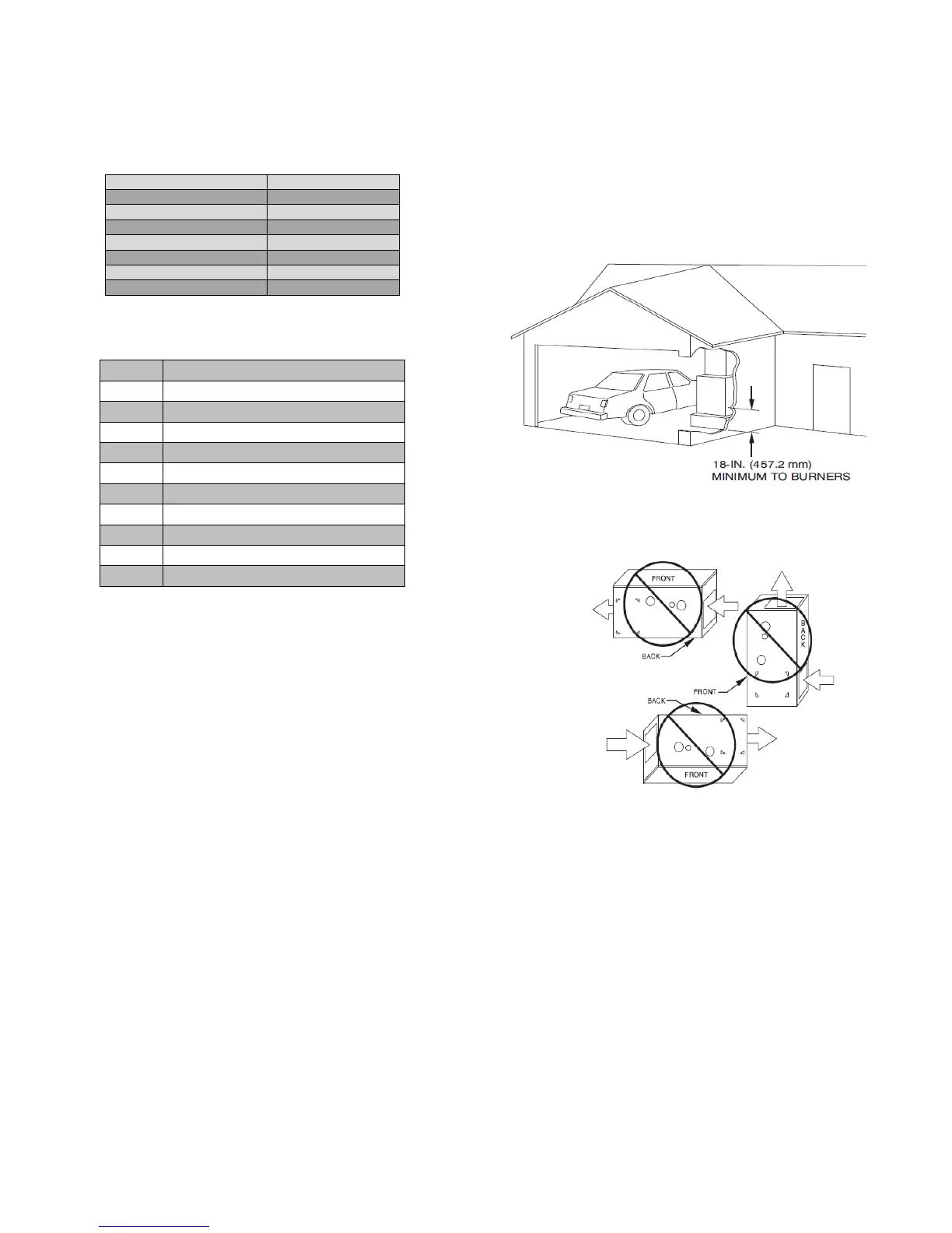
Figure 2 Installation in a garage
Figure 3 Prohibited installation
2.3.1- Location relative to cooling equipment
The cooling coil must be installed parallel with, or on the downstream side
of the unit to avoid condensation in the heat exchangers. The coling coil
should be at least 6” above heat exchanger.
2.4- INTRODUCTION
2.4.1- Direct vent (2 pipes applications)
When this furnace is installed as a direct vent (2 pipes) furnace; no special
provisions for air for combustion are required. However, other gas
appliances installed in the space with the furnace may require outside air
for combustion. Follow the guidelines below to insure that other gas
appliances have sufficient air for combustion.
Direct vent installations require a dedicated combustion air and venting
system. All air for combustion is taken from outside and all combustion
products are discharged to the outdoors.
Therefore, no ventilation or combustion air openings are required.
In Canada, refer to manufacturer's instructions for supporting ULC S636
venting.
 Loading...