35
8.8- PRIME CONDENSATE TRAP WITH WATER
UNIT OPERATION HAZARD
Failure to follow this caution may result in intermittent unit operation or
performance satisfaction. Condensate trap must be PRIMED or proper
draining may not occur. The condensate trap has two internal
chambers which can ONLY be primed by pouring water into the side or
top drain inlet of condensate trap.
NOTE: Temperature rise can be determined for Minimum Heat,
Intermediate Heat and Maximum Heat operation by locking
the furnace in each mode of operation. The mode of
operation is based on the position of Set-up switch on the
furnace control board. The furnace is capable of
automatically providing proper airflow to maintain the
temperature rise within the range specified on furnace rating
plate. If temperature rise is outside this range, proceed as
follows:
a. Check gas input for minimum, intermediate and maximum heat
operation.
b. Check derate for altitude if applicable.
c. Check all return and supply ducts for excessive restrictions
causing static pressure greater than 0.5 in. w.c.
d. Check Troubleshooting Guide for Variable Speed Step
8.8.1- Check safety controls
The flame sensor, gas valve, and pressure switch were all checked in
the Start-up procedure section as part of normal operation.
1. Check Main Limit Switch
a. This control shuts off combustion system and energizes air-
circulating blower motor, if furnace overheats. By using this
method to check limit control, it can be established that limit
is functioning properly and will operate if there is a restricted
return air supply or motor failure. If limit control does not
function during this test, cause must be determined and
corrected.
b. Run furnace for at least 5 minutes.
c. Gradually block off return air with a piece of cardboard or
sheet metal until the limit trips.
d. Unblock return air to permit normal circulation.
e. Burners will re-light when furnace cools down.
f. Check Pressure Switch(es)
g. This control proves operation of the draft inducer blower.
h. Turn off 115 V power to furnace.
i. Disconnect inducer motor lead wires from wire harness.
j. Turn on 115 V power to furnace.
k. Set thermostat to “call for heat” and wait 1 minute. When
pressure switch is functioning properly, hot surface igniter
should NOT glow and control diagnostic light flashes a status
code 32. If hot surface igniter glows when inducer motor is
disconnected, shut down furnace immediately.
l. Determine reason pressure switch did not function properly
and correct condition.
m. Turn off 115 V power to furnace.
n. Reconnect inducer motor wires, replace blower door, and
turn on 115 V power.
o. Blower will run for 90 seconds before beginning the call for
heat again.
p. Furnace should ignite normally.
8.8.2- Checklist
1. Put away tools and instruments. Clean up debris.
2. Verify that blower and control doors are properly installed.
3. Cycle test furnace with room thermostat.
4. Check operation of accessories per manufacturer’s instructions.
5. Review Owner’s Manual with owner.
6. Attach literature packet to furnace.
9- OPERATING YOUR FURNACE
These furnaces are equipped with an ignition device which automatically
lights the burners. Do not try to light the burners by hand.
Before operating, smell around furnace area for gas. Be sure to smell
near floor because some gas is heavier than air and will settle to the
lowest point. See WHAT TO DO IF YOU SMELL GAS on page 44 if the
odour of gas is present. Use only your hand to turn the gas control knob;
never use tools. If the knob will not turn by hand, don’t try to repair it.
Call a qualified service technician. Force or attempted repair may
result in a fire or explosion.
9.1- START UP INSTRUCTIONS
1. STOP! Read the previous safety information.
2. Set the thermostat to the lowest setting.
3. Turn off all electric power to the furnace.
4. Remove the burner compartment access panel.
5. This appliance is equipped with an automatic ignition device.
Do not try to light the burners by hand.
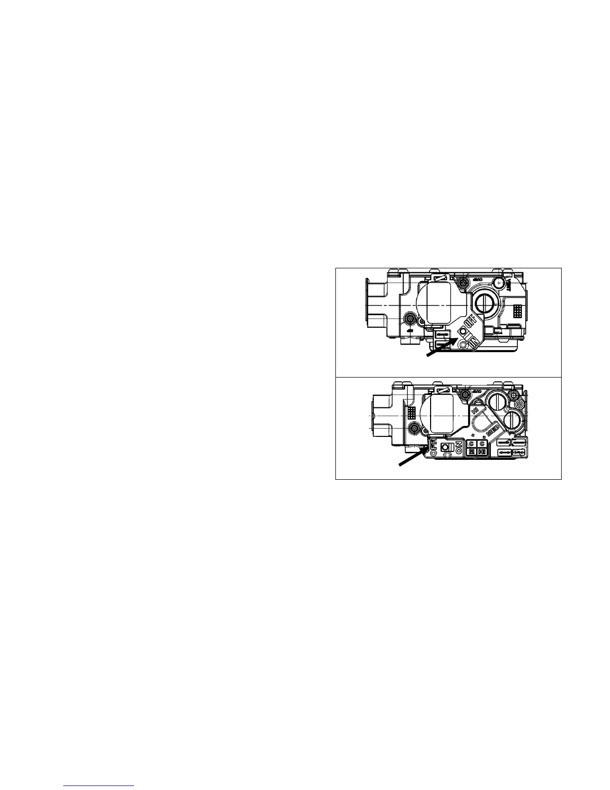
6. Move the gas control switch to “OFF” (see Figure 24).
Figure 24 Control Switch – Modulating Valve
Control Switch - Single Stage Valve
Control Switch - 2 Stage Valve
7. Wait 5 minutes to clear out any gas, then smell for gas (including
at the bottom of the unit near the ground). If you smell gas, stop
and follow the directions in WHAT TO DO IF YOU SMELL GAS
on page 44. If you don’t smell gas, continue to next step.
8. Move the gas control knob or switch to “ON”.
9. Replace the burner compartment access panel.
10. Turn on all electric power to the furnace.
11. Set the thermostat to the desired setting.
12. If the furnace will not operate, follow the instructions found below
in to turn off Gas to Furnace and call your service technician or
gas supplier.
9.2- SHUTTING DOWN THE FURNACE
To shut down the furnace, set the thermostat to the “OFF” position.
9.2.1- To turn off gas to furnace
1. Set the thermostat to the lowest setting.
2. Turn off all electric power to the furnace if service is to be
performed.
3. Remove the burner compartment access panel.
4. Move the gas control knob or switch to “OFF” (see Figure 24). Do
not force.
5. Replace the burner compartment access panel.





 To Next Page