B1
W2 W3
W4
W6
W7 W1
W8
W9
W10
W11
W5
W1
W2
W3
W4
W5
W6
W7
W8
W9
W10
W11
CH 1
CH 2
CH 3
CH 4
CH 5
CH 6
CH 7
CH 8
CH 9
CH 10
CH 11
CH 12
CH 13
CH 14
CH 15
USB
DM
DP
GNDC
RX
TX
RS-485
GNDC
B
B
A
A
POWER
+V
+12 V
GND
P
-12 V
-V
A (RS-485)
GND
C
B (RS-485)
GND
P
+V
+12 V
-12 V
-V
GND
C
GND
C
TX
RX
GND
POWER RS-485 RS-232 RES
GND
Indicator
+9 V
-9 V
CH 0
GND
DE-M040302E • DEWE-5000 • Technical Reference Manual • Printing version 2.2.3 • January 19, 2012
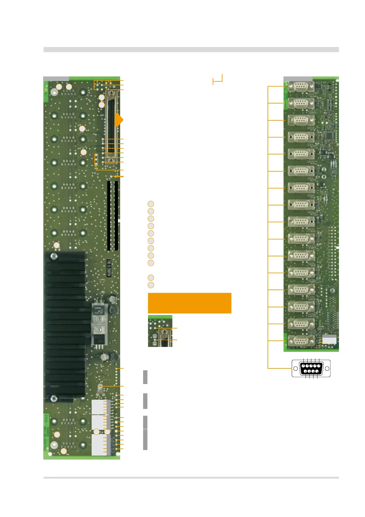
Internal Wiring
16 slot DEWE-MOTHERBOARD DAQ-MOTH-16-DE-x
Internal Wiring
Front viewRear view
9-pin SUB-D pin assignment:
1 Module input (±5 V)
2 RS-485 (A)
3 RS-485 (B)
4 GND
5 +9 V power supply
6 +12 V power (default) /
+V sensor supply
7 Module output
(from A/D board)
8 -V sensor supply
9 -9 V power supply
The 16 slot DEWE-MOTHERBOARD receives the ±12 V
DC
power supply via a DC/DC converter from the
internal power supply.
5 V ORION
Ext. CLK
Ext. TRIG
DGND ORION
Ext. CLK 2 OUT
Ext. CLK 1 OUT (CAMERA TRIGGER)
DGND ORION
16x GND
16 x analog OUT (resistance 50 Ohm)
GND
+15 V ORION
-15 V ORION
16 channels single ended
analog output
(output resistance 15 Ohm)
Please nd the pin-assignment
on the next page!
5 = 5 V output; 330 kHz lter
10 = 10 V output; 330 kHz lter
Terminate RS-485
Connect GND to GND
P
Connect +12 V to +V (pin 6)
Terminate RS-485
Connect chassis to GND
Connect chassis to GND
Connect chassis to GND
Activate ORION RS-485 (A)
Activate ORION RS-485 (B)
Activate analog output 0 on CH 14
Activate analog output 1 on CH 15
Note: If you connect signals to these
contacts you have to open the solder
jumpers W10 and W11 rst!
Connection to CH14 (pin 7)
Connection to CH15 (pin 7)