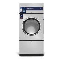
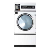
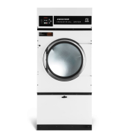
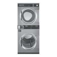
8514-219-001 REV E PAGE 7
INSTALLATION AND OPERATING INSTRUCTIONS
Note: A forklift, or a hand pallet truck or jack, must lift the dryer and only from the
front or rear of the dryer with the dryer bolted to the pallet and supported the full
length of the dryer.
UNCRATING AND PLACING THE DRYER
Tools Required: 3/4" (19 mm) hex socket and ratchet driver, a knife, and a channel-lock
wrench, which will open to 1 3/8" (35 mm).
1. Remove the plastic wrap with the knife. Remove cardboard rails, fillers, and top cap.
2. Using a ratchet and a 3/4” (19 mm) socket, remove the (4) bolts attaching the wooden
skid to the dryer cabinet. Save the bolts for future moving of the dryer.
3. With a walking motion, move the dryer forward completely off the wooden skid. Save the
skid for future moving of the dryer.
4. Using the channel-lock wrench, adjust the leveling legs to align the machine with adjacent
units.
Note: If the dryer is ever moved again, the dryer should be re-mounted on its pallet and its
crating bolts re-inserted and tightened, in the reverse order as above.
Dryer Model Mass Dryer Model Mass Dryer Model Mass
DN0030E_ 210 kg DN0050E_ 263 kg DN0080E_ 331 kg
DRYER INSTALLATION
1. CODE CONFORMITY: All industrial dryer installations must conform to the local and
national codes for the location of installation.
The appliance must not be installed behind a lockable door, a sliding door or a door with a
hinge on the opposite side to that of the tumble dryer, in such a way that a full opening of the
tumble dryer door is restricted.
2. INSTALLATION CLEARANCES: This unit may be installed at the following alcove
clearance.
I. Left Side 0”
II. Right Side 0” *
III. Back 18” (457 mm) (Certified for 1” (25 mm) clearance; however, 18”
(457 mm) clearance is necessary behind the belt guard to allow servicing
and maintenance.)
IV. Front 48” (1220 mm) (to allow use of dryer)
V. Top Refer to figure labeled on the next page “Vertical Clearance Dimensions”.
Certification allows 0” clearance at the top 1” (25 mm) back from the
front. However, a 1/4" (6 mm) clearance is required to allow opening the
upper service door.
 Loading...


