8514-272-001 REV C page 7
INSTALLATION AND OPERATING INSTRUCTIONS
This dryer may have been supplied as part of a washer/dryer stacked appliance. If
so, refer to the washer instructions for uncrating and hard mounting the stacked
unit to a concrete floor and observe the dryer clearances listed below.
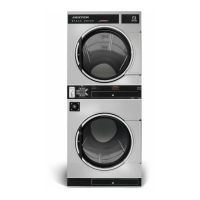
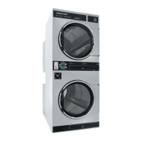
STACK WASHER /DRYER INSTALLATION (when necessary):
1. Place dryer on top of washer and align (4) mounting holes. The front (2) mounting holes are located inside
the lint compartment 5 ½” from the front of the machine. The back (2) mounting holes are located on the
right/left side of the machine, at the base of the back panel. Removing the rear guard is necessary to access
the back mounting hole located opposite the duct work.
2. Use (4) supplied 5/16” x 1-1/4 dog tip bolts to secure the dryer on top of the washer.
DRYER INSTALLATION
1. CODE CONFORMITY. All commercial dryer installations must conform with local codes or, in the absence of
local codes, with the latest edition of the National Fuel Gas Code ANSI Z223.1A. Canadian installations must
comply with current Standard CAN/CGA-B149 (.1 or .2) Installation Code for Gas Burning Appliances or Equipment,
and local codes if applicable. Australian installations must meet installation requirements and pipe sizing
requirements of AS/NZA 5601. The appliance, when installed, must be electrically grounded in accordance with
the latest edition of the National Electrical Code, ANSI/NFPA70, or, when installed in Canada, with Standard CSA
C22.1 Canadian Electrical Code Part 1.
2. INSTALLATION CLEARANCES. This unit may be installed at the following alcove clearance. (millimeters)
I. Left Side 0”
II. Right Side 0” *
III. Back 18” (457) (Certified for 1” (25) clearance; however, 18” (457) clearance is necessary behind
the belt guard to allow servicing and maintenance.)
IV. Front 48” (1220) (to allow use of dryer)
V. Top Refer to figure on the next page labeled “Vertical Clearance Dimensions”.
Certification allows 0” clearance at the top 1” (25) back from the front. However, a 1/4” (6)
clearance is required to allow opening the upper service door.
A 10” (254) clearance is required from the top at all other points.
VI. Floor This unit may be installed upon a combustible floor.
Do not obstruct the flow of combustion and ventilation air.
Maintain minimum of 1” (25mm) clearance between duct and combustible material.
Refer to installation label attached to the rear guard of the dryer for other installation information.
 Loading...