8514-234-001 REV N page 19
INSTALLATION AND OPERATING INSTRUCTIONS
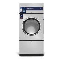
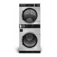
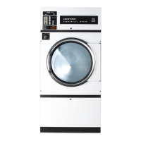
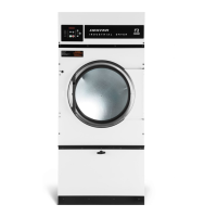
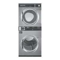
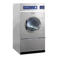
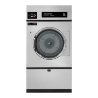
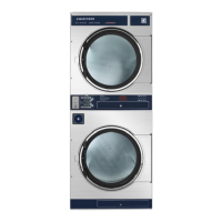
UNCRATING AND PLACING DRYER
Tools Required: 3/4" (19 mm) hex socket & ratchet driver, wood block 4" (100 mm) or 5" (125 mm) thick, a knife
and a groove joint pliers, which will open to 1 3/8" (35 mm).
1. Remove and discard packaging.
2. The crate base is attached to the dryer by (4) cap screws driven upward from below the crate base. Remove
crate base from dryer, by tipping dryer sidewise and place block under crate base rail in center of dryer.
Using a ratchet and 3/4" hex socket, remove and discard (2) crating bolts from side, which is raised.
Remove block from under crate base. Repeat for other side. Save the bolts for use if the dryer is ever
moved again.
3. With a walking motion move dryer completely off crate base. Save the crate base for use if the dryer is
ever moved again.
4. Slide unit into position where it will be installed. Adjust leveling legs, using the groove joint pliers, to level and
align dryer with adjacent units.
Note: If the dryer is ever moved again, the dryer should be re-mounted on its crate base and its crating bolts re-
inserted and tightened, in the reverse order as above.
DRYER INSTALLATION
1. CODE CONFORMITY: All commercial dryer installations must conform with local codes, or in the absence of
local codes, with the latest edition of the National Fuel Gas Code ANSI Z223.1. Canadian installations must
comply with the current Standard CAN/CGA-B149 (.1 or .2) Installation Code for Gas Burning Appliances or
Equipment, and local codes if applicable. Australian installations must meet installation requirements and pipe
sizing requirements of AS/NZA 5601. The appliance, when installed, must be electrically grounded in
accordance with the latest edition of the National Electric Code, ANSI/NFPA70, or, when installed in
Canada, with Standard CSA C22.1 Canadian Electrical Code Part 1.
To connect the dryer to the supply piping, use a listed connector in compliance with the Standard for
Connectors for Gas Appliances, ANSI Z21.24 • CSA 6.10.
The appliance must not be installed behind a lockable door, a sliding door or a door with a hinge on the
opposite side to that of the tumble dryer, in such a way that a full opening of the tumble dryer door is
restricted.
2. INSTALLATION CLEARANCES: This unit may be installed at the following alcove clearances:
I. Left Side 0"
II. Right Side 0"
III. Back 18" (457 mm) (Certified for 1" (25 mm) clearance; however, 18" (457 mm) clearance is
necessary behind the motors to allow servicing and maintenance.)
IV. Front 48" (1220 mm) (to allow use of dryer)
V. Top Refer to figure labeled “Vertical Clearance Dimensions”.
AB. Certification allows 0" clearance for wall framing at the top up to 18" (456 mm)
back from the front.
C. However, a 1/4" (6 mm) clearance should be allowed so that the upper door can
be opened.
VI. Floor This unit may be installed upon a combustible floor.
Do not obstruct the flow of combustion and ventilation air.
Maintain minimum of 1" (25 mm) clearance between duct and combustible material.
Refer to the label attached to the Belt Guard on the rear of the dryer for other installation information and
start-up instructions.
 Loading...


