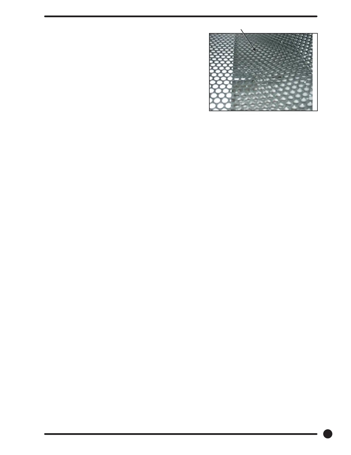
Sensor located under drum
Temperature Sensor Removal
UPPER - Remove front panel upper. Once front panel is
removed, reach through the right side and back into the
area where the sensor is mounted and remove wire nuts to
disconnect.
LOWER - To remove the lower temperature sensor it is
necessary to remove the lower front panel to gain access to
the mounting bracket. Then the bracket is removed as on the
upper cylinder.
Upper Front Panel Removal
1. Remove the loading door from the panel.
2. Remover the Dryer control board.
3. Remove the 4 phillips screws, 2 on the righ and 2 on the left. Once panel is loose remove the
door switch wires.
The trim does not have to be removed. (The panel may be removed with the
door left in place, although it is much heavier and more awkward to do so.)
Lower Front Panel Removal
To remove the lower front panel a procedure similar to the upper may be used. However, the bottom of
the upper panel must be loosened and pulled out to allow the upper ange of the lower panel clearance to
be removed.
NOTE: Always remove power from the machine before changing drive belts or
working with the drive system.
Final Drive Belt Replacement
To replace the nal drive belt turn the cylinder slowly by hand and work the belt o of the large pulley.
Motor Drive Belt Replacement
To replace the motor drive belt the nal drive belt should be removed as above. Cut the old motor belt and
remove. The new motor drive belt ts inside of three of the four motor mounting bolts. To achieve this,
remove these three bolts one at a time and slide the belt in past each in turn. In this way the motor is
always supported by 3 bolts at any time.
NOTE: All drive belts are self adjusting.
Tumbler Pulley Removal And Installation
Remove the 1 1/2” nut and lock washer. Pull the pulley o the shaft. Watch for the locking key on the
tumbler shaft. Upon installation, the tumbler nut should be torqued to 150 ft./lbs.
Note: After Serial #226213 Remove bolt and washers holding pulley to cylinder shaft. Reincert bolt then
using two or three jaw puller Pull pulley straight o of shaft.
Intermediate Pulley And Tension Arm Removal
1. The intermediate pulley is retained with a snap ring. Remove the snap ring and the pulley slides
o the shaft.
2. With the pulley o, there is access to the self adjusting tension arm assembly. The tension arm
assembly may be removed by removing the snap ring that holds it to the tension arm support
assembly pin. The arm assembly is replaced as a complete unit.
3. The grease tting for the intermediate shaft should be greased monthly.
61
Part # 8533-090-001 7/21
 Loading...