18
Quick Setup Guide
Quick Setup
Guide
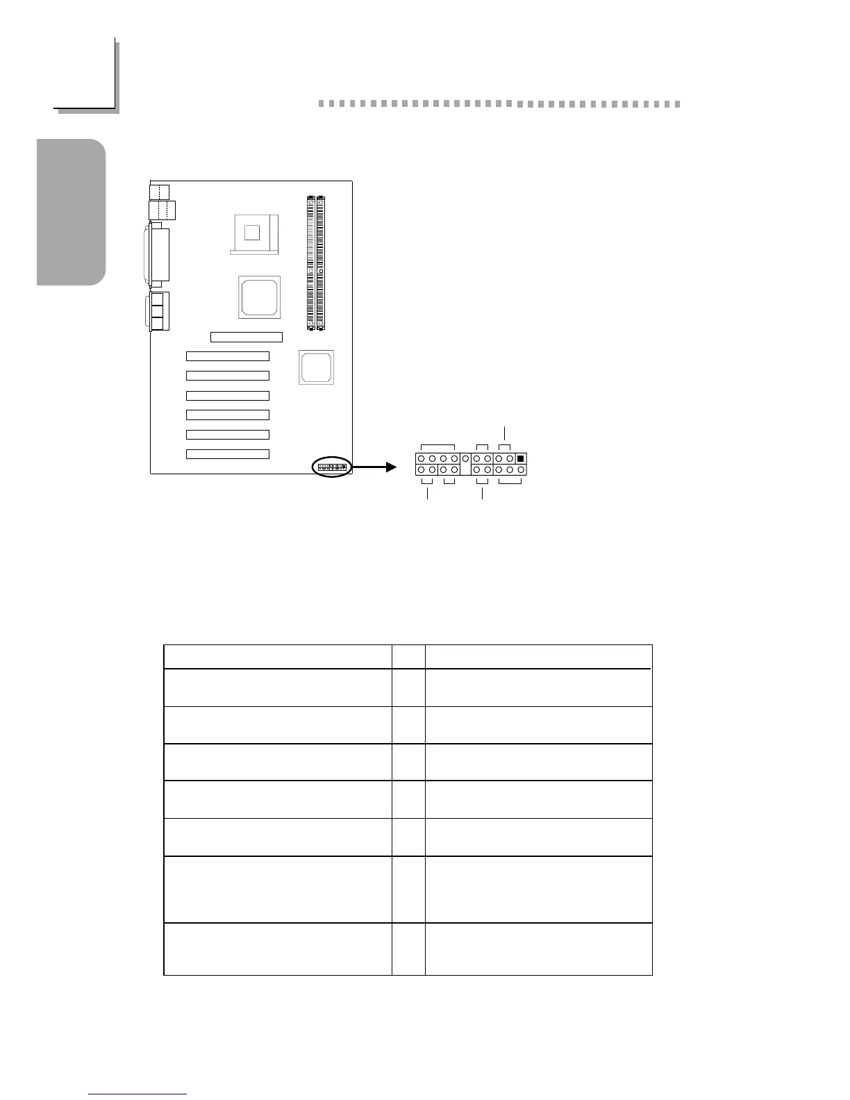
1.4.9 Front Panel Connectors
If a system did not boot-up and the Power/Standby LED did not light after it
was powered-on, it may indicate that the CPU or memory module was not
installed properly. Please make sure they are properly inserted into their
corresponding socket.
PWR-LED
G-SW
HD-LED
RESET
SPEAKER
2
1
20
19
ATX-SW
G-LED
Front panel
connectors (J16)
Pin
3
5
14
16
8
10
18
20
7
9
13
15
17
19
2
4
6
HD-LED
(Primary/Secondary IDE LED)
G-LED
(Green LED)
ATX-SW
(ATX power switch)
G-SW
(Green switch)
RESET
(Reset switch)
SPEAKER
(Speaker connector)
PWR-LED
(Power/Standby LED)
Pin Assignment
HDD LED Power
HDD
Green LED Power
Ground
PWRBT+
PWRBT-
Ground
SMI
Ground
H/W Reset
Speaker Data
N. C.
Ground
Speaker Power
LED Power (+)
LED Power (+)
LED Power (-) or Standby Signal