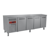
H. PROBE REPLACEMENT (OPERATIONS ON POINT A ARE TO BE ACCOMPLISHED FIRST)
H1. After extracting the
thermoregulator disconnect the
probe from the terminal
H2. Unscrew the protection carter
of the probe ( unit display’s left
compartment) and disconnect
H3. Fasten the probe and
carterpassing along the lead
from the suitable hole on the
bottom crossbeam
H4. Reconnect the probe to the
thermoregulator
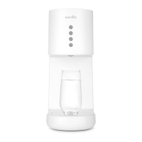
I. FAN REPLACEMENT
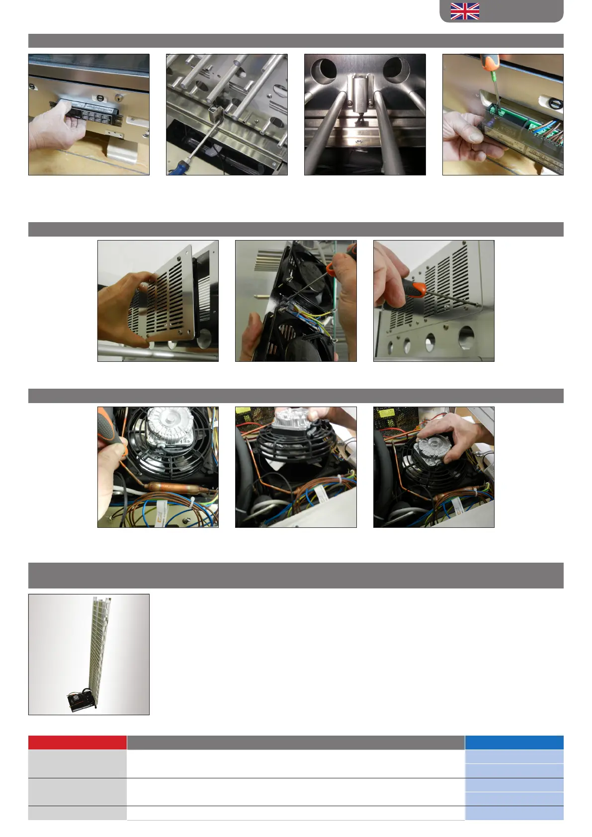
L. CONDENSATOR FAN REPLACEMENT (OPERATIONS ON POINT A ARE TO BE ACCOMPLISHED FIRST)
I1. Unscrew the fans carter and
extract
I2. Disconnect the electric cables
and unscrew the carter fans
I3. Reconnect the fans, tighten
them andreassemble the carter
M. CONDENSATOR REPLACEMENT / COMPRESSOR / COOLING COIL
(OPERATIONS ON POINT A - B ARE TO BE ACCOMPLISHED FIRST)
After extracting the unit display cooling system , retrieve the
refrigerating gas following the legislation in force.
Proceed to the compressor/condensator replacementcarefully replacing
the dehydrating lter.
Once the refrigerating circuit in reconnected test the tightness of
thecooling system. Empty the circuit using a vacuum pump, at this stage
reload the cooling system using the same type of refrigerating gas and
the same amountrecommendedon the plate placed on the external
metallic tank.
The following documents are available on the internet website www.exposrl.com
Document Type Browser link File Name
Exploded view www.exposrl.com >> technical area >> Spare parts and exploded views
P#AR1#
P#R2#
Wiring diagram www.exposrl.com >> technical area >> electric wiring
PV-CV (SE)
PC-S-G (SE)
Usernstruction Manual www.exposrl.com >> technical area >> user instructions PCV (MI)
L1. Unscrew thespecic screw
placed on the fan protection
grid
L2. Extract the fan rotating it
counterclockwise
L3. Assemble the new fan,screw
back and reconnect to the
electrical wiring
ENGLISH
 Loading...