Do you have a question about the Diamond BCC/10 and is the answer not in the manual?
Provides information for after-sales activities and repair procedures.
Details safety precautions, fire hazards, and general warnings for safe operation.
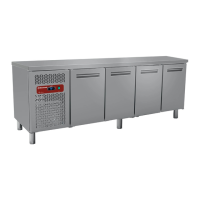
Explains the meaning of various information found on the unit's data plate and its technical data.
Instructions on how to locate and access the USB port for data download.
Procedure for removing the cover to access the USB KEY slot.
Explains automatic download initiation upon USB key insertion and conditions for operation.
Warning against inserting the USB key before turning on the appliance to avoid alarms.
Details the folder structure on the USB key for downloaded HACCP data.
Lists displayed alarms (B5, B6, B7, E13) and their respective causes.
Step-by-step procedure to download all logged alarms from the USB key.
Describes the folder structure created after download, including Alarm Log Report.
Details parameters for setting USB export frequency, sampling, and language.
Explains serial communication lines for HACCP network control station connection.
Confirms data history is memorized on the datalogger COP_U40 and not lost upon replacement.
Provides a visual representation of the Data logger COP_UI40.
Details the dip switch settings for the UI40, recommending a standard configuration.
Diagnoses communication errors based on LED status and suggests component checks.
Interprets the meaning of LED 1 blinking red, indicating microprocessor activity.
Indicates that LED 7 being red signifies an issue with the COP_UI40 board supply.
Reference table for parameter settings related to the buzzer kit.
Guidance on connecting the buzzer cable, following color and label indicators.
| Brand | Diamond |
|---|---|
| Model | BCC/10 |
| Category | Commercial Food Equipment |
| Language | English |