10
Automotive Circuit Probe & Breaker Finder Kit
If the resistance value is greater than 100KΩ, the LCD will show “0L”.
There is also another way to prove continuity of connections to ground or batte.Power up
the connection using the power switch. If the circuit breaker trips, you have a good solid low
resistance connection.
Note: You can use the probe tip to pierce the plastic insulation on a wire. This means that
you can test the circuit without disconnecting anything.
Figure 10
If the LCD readings are abnormal, there is a problem with this sensor.
3.3 Signal Circuit Testing
Once you extract a DTC from the vehicle and realize that troubleshooting begins with some
kind of sensor circuit, there is a quick test you can peorm to verify the code. Testing your
sensor is easy while using the tool.
For example, you suspect there is a problem with your M.A.P. sensor circuit, then follow the
procedure below to test this sensor:
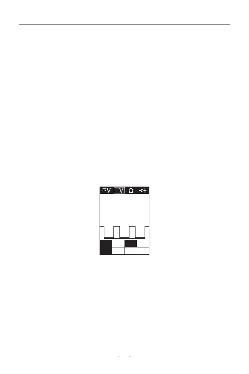
◆ Set the tool in AC Voltage mode, using the probe tip and the auxilia ground lead.
◆ Connect vacuum pump to MAP sensor.
◆ Contact the probe tip to the MAP sensor positive terminal and obsee the LCD readings
which should be a sine wave in normal condition.
◆ Apply vacuum.
◆ Release vacuum and obsee the LCD readings. (Figure 10)
3.4 Activating Components in Your Hand
While the circuit probe is in DC voltage mode, by using the probe tip in connection with
the auxilia ground lead, components can be activated right in your hand, thereby
testing their functions.
Connect the auxilia ground lead to the negative terminal or ground side of the compo-
nent being tested. Then contact the probe tip to the positive terminal of the component,
Max 12.4 Freq Hz
Min 0.2 43.0K