Do you have a question about the DIEBOLD NIXDORF D2156 and is the answer not in the manual?
Details general authorization, FCC Class A declaration, and tested safety symbols like CE and cTUVus.
Provides essential safety precautions, handling guidelines, and warranty terms for the device.
Outlines proper cleaning methods and environmentally responsible disposal procedures for the display.
Details the product, supplier information, and FCC compliance statement as per regulations.
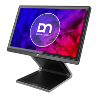
Introduces the D2156 display, its features, and its application in various retail environments.
Lists the key features of the D2156 display, including its low footprint, flicker-free operation, and connectivity options.
Explains the manual's content, purpose, and the meaning of different warning and note symbols used throughout the document.
Provides a visual overview of the D2156 display, its screen size, resolution, and touch screen technology.
Describes the front panel of the D2156 display, focusing on the power button and activity LED.
Explains the behavior of the power button LED under different conditions and the function of the ON/OFF button.
Details the connector panel of the D2156 display, listing all available ports and their functions.
Introduces the GUI software tool for configuring display settings and lists available customization options.
Provides a detailed table of display settings, their descriptions, and default values.
Explains the RMT feature allowing the display's power button to control the BEETLE system.
Describes how to lock or unlock the display's power button, affecting manual control and RMT signal.
Discusses the benefits and general information about the projected capacitive touch screen technology.
Provides instructions on how to use the touch screen and guidelines for proper cleaning to avoid damage.
Guides the user through unpacking the display and verifying the delivery contents.
Details the steps for installing the D2156 display onto its standard stand, including preparation.
Outlines the steps to prepare the display for mounting onto the stand, including screw removal.
Describes how to fit and secure the display to the stand using screws and access the connector panel.
Covers removing cable covers, connecting USB-C cables, and returning the display to its operating position.
Details the initial steps for installing the display to the stand, focusing on removing specific covers.
Outlines the steps to prepare the display itself for attachment to the stand, including screw removal.
Describes fitting the display to the stand, tightening screws, and accessing the connector panel.
Guides on routing cables through the stand and replacing the cable covers to complete the installation.
Details tucking cables, replacing the VESA cover, and aligning/replacing the back cable cover.
Provides a note on switching off the display and disconnecting power before connecting cables.
Offers guidelines for wall mount configuration, specifying installation height and screw requirements.
Provides recommendations for setting up the terminal workplace, focusing on avoiding glare and screen positioning.
Details the installation process for the Waiter Lock module, used for system access control.
Explains how to gently remove the side cover of the Waiter Lock module using a small screwdriver.
Details the process of removing the side-attach peripheral connection cover from the system.
Guides on inserting, fitting, and securing the Waiter Lock module with screws.
Covers re-attaching peripheral and side covers to finalize the Waiter Lock module installation.
Shows the front view of the system after the Waiter Lock module has been successfully installed.
Explains how to operate the MSR module, including card swiping techniques and cleaning instructions.
Details the removal of the MSR module's side cover and the system's peripheral connection cover.
Guides on inserting, fitting, and securing the MSR module, followed by re-attaching covers.
Describes the NFC module kit and the initial steps for installation, including removing the module's side cover.
Details sliding out the NFC module's side cover and removing the system's peripheral connection cover.
Explains how to insert the NFC module into the exposed USB port and fit its knobs into the system's grooves.
Describes tightening screws to secure the NFC module and re-attaching covers to complete the installation.
Explains the installation of the BCR module, its attachment, and swivel capabilities, with a warning.
Details the steps to remove the BCR module's top cover by inserting a screwdriver into slots.
Covers sliding out the BCR top cover, removing the system's connection cover, and docking the BCR module.
Explains how to swivel the BCR scanner to access locking screws and then tighten them.
Details snapping back the BCR top cover and illustrates the swivel angles for the BCR scanner.
Introduces the Fingerprint Reader module and its role in secure login and identification in retail.
Provides instructions for cleaning the fingerprint sensor using optical cleaning products and specific solutions.
Lists important cautions regarding the cleaning of the fingerprint sensor to prevent damage.
Guides on unpacking the Fingerprint kit and removing the module's side cover as the first step.
Details sliding out the Fingerprint module's side cover and removing the system's peripheral connection cover.
Explains how to insert the Fingerprint module into the USB port and fit its knobs into the system's grooves.
Guides on positioning the module and tightening the screws with specified torque to secure it.
Details re-attaching the side cover to finalize the Fingerprint module installation and shows the final front view.
Provides comprehensive technical specifications for the D2156 display, including dimensions, operating conditions, and performance.
Illustrates the dimensions of the D2156 display for both wall and stand mounting configurations.
Details touch screen specs and lists supported display resolutions with notes on scaling quality.
Details supported standards, host interface, voltage, current, operating temperature, and OS for the NFC module.
Presents a dimensional drawing of the NFC module, showing its physical measurements.
Lists comprehensive technical specifications for the 2D Barcode Reader, including voltage, interface, and dimensions.
Provides a dimensional drawing of the 2D Barcode Reader, illustrating its physical dimensions.
Details the technical specifications for the iButton module, including voltage, interface, OS, and dimensions.
Presents a dimensional drawing of the iButton module, showing its physical measurements.
Lists the technical specifications for the Magnetic Swipe Card Reader (MSR) module, including voltage, interface, and dimensions.
Provides a dimensional drawing of the MSR module, illustrating its physical dimensions.
Details the technical specifications for the Fingerprint Reader module, including voltage, current, sensors, and dimensions.
Presents a dimensional drawing of the Fingerprint Reader module, showing its physical measurements.
| Brand | DIEBOLD NIXDORF |
|---|---|
| Model | D2156 |
| Category | Monitor |
| Language | English |