Peripherals (optional)
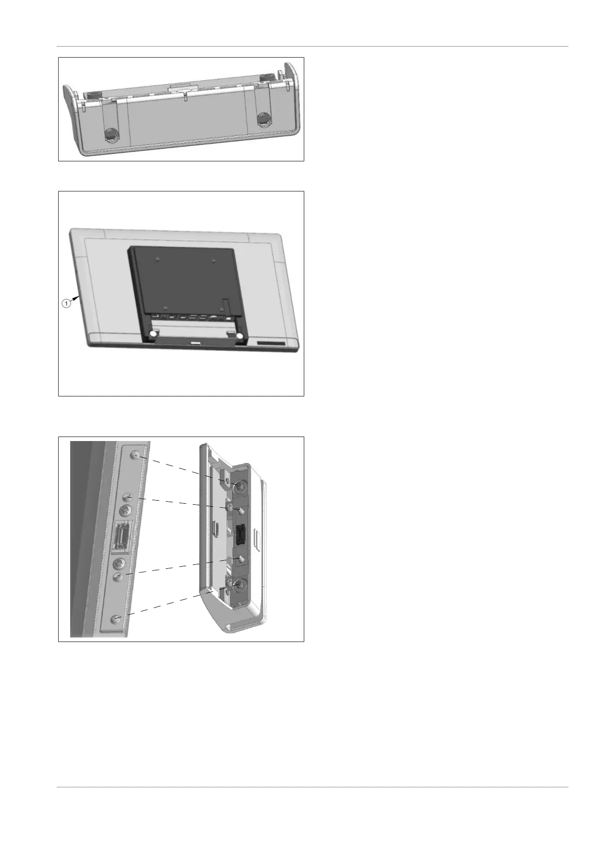
Figure10-11: Removing side cover of MSR module
2. Gently remove the side cover of the MSR
module found on the other side.
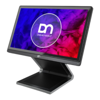
Figure10-12: Removing the side-attached peripheral connec-
tion cover
3. Remove either side-attach peripheral con-
nection cover (1) of the system.
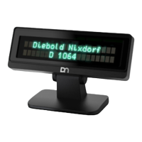
Figure10-13: Fitting the MSR module into the system
4. Insert the MSR module into the now exposed
USB port of the system.
5. Fit each knob on the MSR module into its re-
spective groove on the system as indicated.
Confidential External
Copyright © 2023, Diebold Nixdorf
01750368517 B
10-7


 To Next Page