Using the 888/24 I/O
7
5
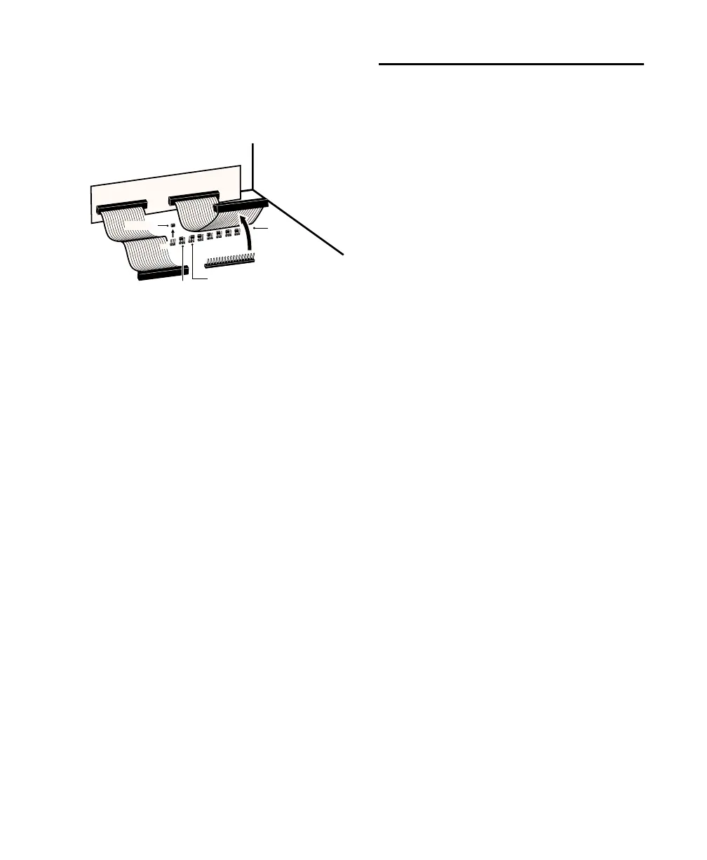
With the ribbon cable out of the way
you’ll see eight 3-pronged jumper switches,
each with a removable cap. Locate the
switch for the channel you wish to modify.
6
Gently lift the cap off of the jumper
switch. Place it in the position correspond-
ing to the operating level that you desire.
For +4 dBu levels, it should be placed over
the left two prongs. For –10 dBV levels, it
should be placed over the right two prongs.
7
After you have made the desired changes,
reconnect the ribbon cable and put the top
back on the 888/24 I/O.
8
Replace the four front panel screws using
the hex wrench.
9
Replace the top screws with a Phillips
screwdriver.
Making Signal Connections
to the 888/24 I/O
Depending on how you plan to use the
888/24 I/O, the way you connect it to your
studio will vary.
Choosing between +4 dBu and
–10 dBV operation modes
The 888/24 I/O can be set to operate at
+4 dBu or –10 dBV input and output levels.
It is important that you determine which
line level mode is appropriate for your stu-
dio. In +4 dBu operating mode, the
888/24 I/O is a 24-bit digital audio device
capable of producing audio signals at or
near +26 dBu.
Check the owner’s manual for your mixer,
power amplifier or effects processor to see if
it can handle this load. If it cannot, con-
sider setting the 888/24 I/O to operate at
–10 dBV line levels.
Consider the following when connecting a
mixer:
◆
If your mixer cannot handle more than
1.5V (RMS) inputs at +4 dBu, then you
should set the 888/24 I/O to run at –10 dBV
line level.
◆
If your mixer can handle up to 8.5V
(RMS) inputs, or has pads or attenuators on
its inputs, then you can use the +4 dBu set-
ting on the 888/24 I/O.
Most manuals contain device input specifi-
cations, including whether or not there are
pads or attenuators. Consult the manufac-
turer of your mixer or power amplifier for
further information.
Setting the output level jumper switches
detach
ribbon cable
remove jumper
+
4
-1
0
place jumper
in this position
to set output
to +4 dBu level
place jumper
in this position
to set output
to -10 dBV level
 Loading...