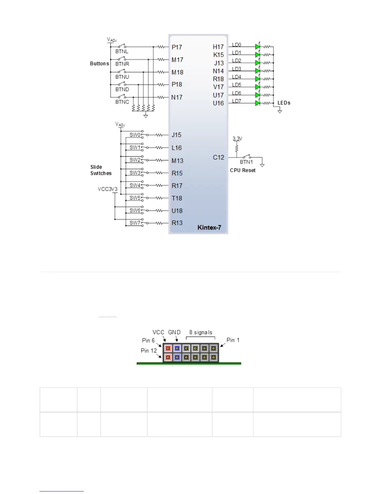
The eight individual high-efficiency LEDs are anode-connected to the FPGA via 330-ohm resistors, so they will turn on when
a logic high voltage is applied to their respective I/O pin. Additional LEDs that are not user-accessible indicate power-on,
FPGA programming status, and USB and Ethernet port status.
The Pmod connectors are arranged in a 2×6 right-angle, 100-mil female connectors that mate with standard 2×6 pin headers.
Each 12-pin Pmod connector provides two power pins (6 and 12), two ground pins (5 and 11), and eight logic signals, as
shown in Figure 20. The
VCC () and Ground pins of can deliver up to 1A of current per pin. Pin assignments for the Pmod
I/O connected to the FPGA are shown in Figure 16.
The Genesys 2 features four Pmod connectors of different “styles” with subtle differences between them. Table 10 summarizes
these differences.
Pmod
conector Power Analog/Digital Routing
Series
protection Recommended usage
JXADC VADJ Dual Differential; Pairs:
1-7,2-8,3-9,4-10
100 ohm Analog inputs; LVDS_25
input/output (VADJ=2.5V)
14. Pmod Connectors
Page 2
of 3