INSTALL GUIDE
Keypad & RFID
|
Basic & Advanced
8
Front View
2 3
4 5
Rear View
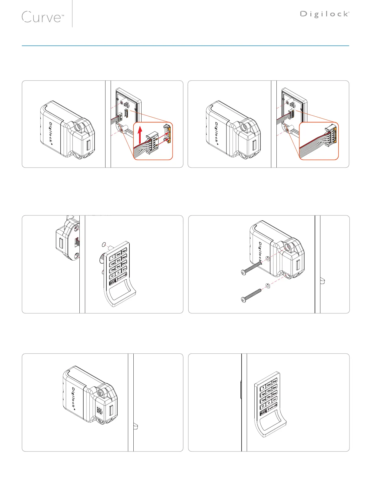
ATTENTION: The rear-unit connector must be oriented with the red wire positioned on the top of the
ribbon cable (as highlighted in g-1). Improper connection may result in the lock to improperly function.
With the cable connector properly oriented. Insert the rear units
cable connector to the corresponding front units pin-connector
(as highlighted in fig-1).
The LED will flash red 3 times accompanied with a three-tone
beep, then followed by the LED flashing green 3 times.
Note: The audible/visual feedback may only indicate that the
metal pin's have made contact. It is necessary to further insure
that both connectors are properly seated and connected
(as highlighted in fig-2).
For illustration, a keypad front unit with a bolt rear unit is shown�
Insert the front units nut-post through the doors mounting holes.
Hold and align the rear-unit using the same mounting holes
Note: To avoid pinching of the ribbon cable a recessed pocket is
provided behind the rear unit.
Insert the screw with lock-washer through the mounting holes.
Tighten screws to the torque level of: 21.4 kgf/cm² ±20%
Note: Overtightening of the mounting hardware may result in
the lock to improperly function.
Use the screw chart
to select the proper
screw length for your
door thickness.
Rear View
6
Front View
Test the lock while the door is open to ensure that the bolt or latch is operating properly. Refer to the testing instructions below.
Once installation is complete, refer to the DigiLink Site Setup Guide to add locks.
fig-1 fig-2
LOCK INSTALLATION STEPS