Page 4
Connections and Controls
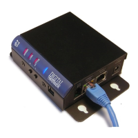
Refer to the preceding pictures.
Provides for low level firmware flashing
as well as viewing technical support
information. Will also power the unit
for diagnostic purposes.
I2C expansion bus interface that can be
used for custom applications. Requires
custom firmware from Digital Acoustics
10/100 Ethernet network interface.
Supports auto negotiation and auto-
MDIX. PoE enabled
Provides a 10/100 Ethernet network
connection for another device. Supports
auto negotiation and auto-MDIX
2.1mm power connector with center tip
positive. 12VDC @ 1.2 amps or 24VDC
at 2.5 amps. Overrides PoE power.
Warning: Connecting power to both
the 2.1mm Power jack and the J1-1 and
J1-2 power connectors at the same time
will damage the unit
Allows unit to be snapped on to
standard 35mm DIN Rail stock
The ST MIC switch is in the MIC
position by default. If using single
transducer mode (speaker used as both
a speaker and microphone) use a small
screwdriver to move the recessed
switch to the ST position (towards the
DIN clip).