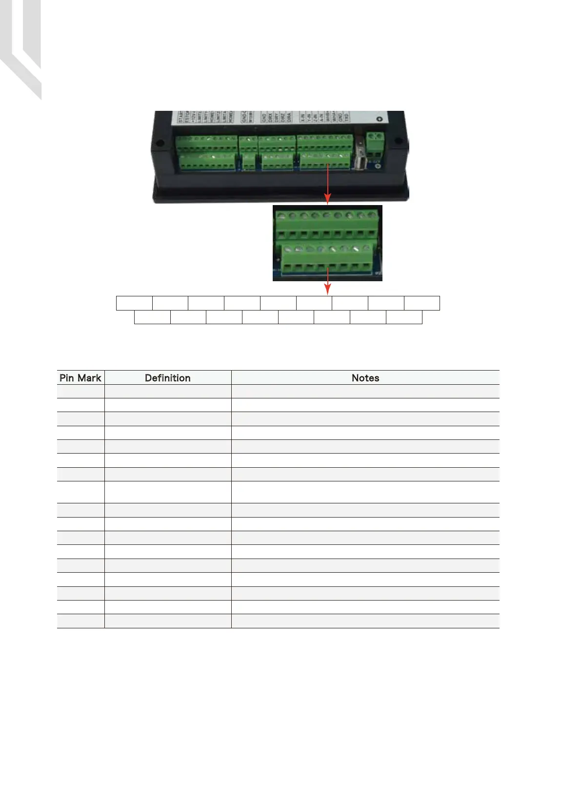
The MPG port picture is shown in Picture 2-5. It is the 8+9 double row screw terminals next to the
USB port.
The MPG port has 17 screw terminals, see Table 2-1 for reference. See Table 2-2 and table 2-3 for the wiring.
2.2.3 MPG Port
Picture 2-5 MPG port
Table 2-1 Cr8-500’s MPG Port
Pin Mark Definition Notes
ESTOP of MPG Connect with GND,ESTOP is in effect.Open indicates Estop is invalid
Select switch 1 X Connect with GND, indicates selecting1 X, open indicates no pulse
Select switch 10 X Connect with GND, indicates selecting10 X, open indicates no pulse
Select switch 100 X Connect with GND, indicates selecting100 X, open indicates no pulse
MPG Ground MPG power supply ground, so it is the switch signal reference ground
MPG B phase negative MPG B phase differential input negative terminal
MPG A phase negative MPG A phase differential input negative terminal
MPG power supply 5V output
Exclusive use supply terminal of MPG, which can restore the fuse
connection with a 200MA of the system power supply.
MPG serial communication input Used for digital display of theMPG communication
Select switch of X axis Connect with GND, indicates selecting X axis, open indicates no selecting
Select switch of Y axis Connect with GND ,indicates selecting Y axis, open indicates no selecting
Select switch of Z axis Connect with GND, indicates selecting Z axis, open indicates no selecting
Select switch of A axis Connect with GND, indicates selecting A axis, open indicates no selecting
MPG B phase positive MPG B differential input positive terminal
MPG A phase positive MPG A phase differential input positive terminal
MPG ground MPG power supply reference ground.
MPG serial communication output Used for digital display of the MPG
ESTOP
X10
X100
Ground
B phase-
A phase-
+5V-W
RXD
X select
Y select
Z select
A select
B phase+
A phase+
ground
TXD
X1
ESTOP X1 X10 X100 GND WHB- WHA- +5V-W RXD
X-IN Y-IN Z-IN A-IN WHB+ WHA+ GND TXD
Page -7Digtital Dream 4 Axis Motion Controller DDCS V2.1 User’s Manual
 Loading...


