1–6 DECserver 90M Owner’s Manual
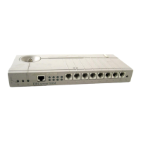
Table 1–1: Controls, Indicators, and Connectors
Item Description
1 Power Indicator Turns on when +5 volts are supplied to the
DECserver 90M.
2 System OK Indicator Turns on when the DECserver 90M successfully
completes the ROM-based self-tests.
3 Network OK Indicator Turns on when you connect the DECserver 90M
to a properly terminated network. Blinks while
the DECserver 90M loads or dumps software.
4 Ethernet Address Label Displays the DECserver 90M Ethernet address.
5 10BaseT Connector Connects the DECserver 90M to the network.
Not used when you install the DECserver 90M in
a DEChub 90 Ethernet backplane.
6 Port Activity Indicators Consists of eight LEDs, each corresponding to a
device port on the DECserver 90M. Each port
activity LED turns on when the associated port is
in use. These LEDs blink when port activity is
detected and continue blinking until port data
transfer stops.
7 Port Connectors (MJ8) Connects the peripheral devices to the
DECserver 90M.
8 Power Connector Connects the power source to the standalone
DECserver 90M. Not used when you install the
DECserver 90M in a DEChub 90 Ethernet back-
plane.
9 Backplane Connector Connects the DECserver 90M power source and
network interface to a DEChub 90 Ethernet
backplane.
10 Back Cover Covers the backplane connector and mounting
assembly. Present on standalone units only.
11 Reset Switch Resets the DECserver 90M to the factory-default
characteristics.
12
Network Connector (BNC) Connects the DECserver 90M to the ThinWire
network. Not used when you install the DEC-
server 90M in a DEChub 90 Ethernet backplane.